
Skybadger Observatory
one of the key instruments used in astronomy is the spectrometer. This instrument is designed to split light into its component colours and in doing so, revealing the variations in intensity with colour (wavelength) that indicate the chemistry and conditions at the locations the light was created. Spectrometers are slightly involved builds because of the number of optical components, the need for alignment and the need for matching with the telescope they are to be used on to avoid loss of light. In the last decade multiple designs have become available through open source channels for creation through 3d printing by amateurs. Prior to that they werea lso available but as more of a machining and metal work exercise. The LowSpec is one of these 3d designs. Of standard littrow design , using collimators to focus the light from a slit onto a tiltable grating which is then re-imaged on to a main camera, the lowspec fits all this into a 3d printed plastic body with a reflective slit back surface to use as a mirror for guiding using the stars that don't pass through the slit.
The design is on thingiverse www.thingiverse.com as designed by PJH Gerlach.
I built mine using a Creality Ender 3 in stock configuration and using PLA. I figured the cost of the printer and the spectrometer would be recovered vs buying a DACOS from Baader or the Shelyak Instruments Lowres spectrometer and I would still have the printer for many other uses
The optics I purchased mostly from Newport as per the BoM, also from Edmund optics and eventually I have acquired a full set of gratings to cover the optical spectral range from 350nm (blue) to almost 1um (through red to IR ) at resolutions from 500 to 13000.
Examples of this spectrometer fully built also turn up on the online sales fora such as Astrobuysell.
The optical layout is designed for light coming out of the source telescope at f/10. Matching the focal ratios maximises throughput.
I actually use mine at f/6.7 with a focal reducer on the f/10 12.5" RC telescope since I really don't want to try guiding at 3000mm dfocal length right from the start.
The authors optical layout image is reproduced below.
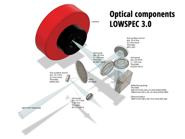 The core concepts are the focusing of the star on the slit, the slit is indexed for rotation against various slit widths, and using the reflected portion from the back of the slit as the guider source image. The rest is just collimiation and folding of the the slit image into the grating and then re-focusing onto the camera.
Since the turntable the grating sits on is driven by a tangent arm, the angle is not linear with the micrometer used to drive the tangent arm. this doesnt; represent a design or implementation problem but it means that calibration is especially important and willchange non-linearly if the offset is not maintained.
The core concepts are the focusing of the star on the slit, the slit is indexed for rotation against various slit widths, and using the reflected portion from the back of the slit as the guider source image. The rest is just collimiation and folding of the the slit image into the grating and then re-focusing onto the camera.
Since the turntable the grating sits on is driven by a tangent arm, the angle is not linear with the micrometer used to drive the tangent arm. this doesnt; represent a design or implementation problem but it means that calibration is especially important and willchange non-linearly if the offset is not maintained.
The print of the main body took my little printer the best part of 3 days and when it was complete I had the devil of a job to get it off the platten. Some of the parts use fine threads in plastic whci I turned up a metal tools to chase and followed up with a thread gauge just to clear and smooth any remaining loose and stringing material. Even so, some of the threads are not well formed. also the main imaging camera ia a large weight to hang at a right angle off the main body so I have had this joint fail at least once. online updates to this replace the plastic with metal tubes that glue or interference fit into the main body of the spectrometer for strength.
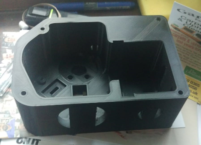 Main body shell after printing showing the recess for the grating turntable, the recess for the 2nd collimator lens and to the right, the slot for the slit wheel mech and folding mirror.
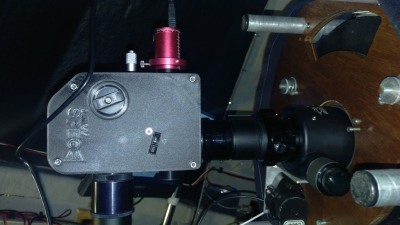 In the picture you can see the spectrometer mated to the back of the telescope in the focuser;
the red camera is the guide scope and on the opposite side, the black tube hanging down is the nose stub for the main imaging camera.
the black tube into the focuser is a 2" nose stub with teh focal reducer and further tube extender used to reach focus. Nowadays this tube is all te way into the focuser since I have moved the telescope mirrors about as I achieve optimal spacing.
In the picture you can see the spectrometer mated to the back of the telescope in the focuser;
the red camera is the guide scope and on the opposite side, the black tube hanging down is the nose stub for the main imaging camera.
the black tube into the focuser is a 2" nose stub with teh focal reducer and further tube extender used to reach focus. Nowadays this tube is all te way into the focuser since I have moved the telescope mirrors about as I achieve optimal spacing.
The spectra I have been collecting from this spectrometer are much more detailed than my original efforts using transparent gratings at the focal plane (See my other web page for these). The calibration constants are modelled using the Ken Harrison spreadsheet that describes the key parameters for the telescope and transfer optics used with each of the potential slits. Link to SimSpec v4 Excel Spreadsheet In use the apparent resolution as measured simply from the dispersion over the number of pixels and estimates of narrowest line width seem to tally quite well.
The key challenges to using this spectrometer are Its a heavy weight to hang off the back of the scope by the time the cables and cameras are added. alignment of grating to the spetral feature of interest is a delicate manual activity Focusing of the spectrum onto the camera can be done in daylight but focusing of the star onto the slit can only take place at night. Integratin of a spectral standard calibration lamp such as a RELCO neon bulb is advisable somewhere in the optical train. This makes the spectroscope suitable for a degree of automation to make life easier in or remote from the observatory.
The RELCO lamp is a brand name for a generic type of neon bulb, often found in fluorescent lamp starter units. The key features are that the gas in the bulb emits light at wavelengths that spread across the visible spectrum and are relatively easy to identify. Due to their small size they can be incorporated into the light train at an approporiate point. However the callibration source position should be aligned to the plane of the grating since they will project an offset spectrum through the grating that will otherwise need to be calibrated out, which also means usig multiple sources to increase the brightness only works if they are all in the same plane.
The neon lamp needs a high voltage AC supply to operate, typically above 80v and up to at least UK/US mains voltage of 120/240. Once on the lamp can runaway and burn out as conductance increases unless you put a limiting resisitor in series to limit the current to a few milliamps per bulb. There are numerous small inverters avaiable for cars and caravans that take s12v in put and generate 240v output as well as dedicated electro luminiescent wire inverters that take 3v battery, 5v USB amnd up to 12v as DC power supplies. I am using an EL wire driver since its small, I already have it and it can supply two lamps at a time. I have also purchased an in-car inverter which is disasembled and ready for re-boxing with a remote power switch as well as a couple of units from Ali-express which are 12v discrete packaged units. Right now I am packaging a cluster of lamps with their ballast resistor around one end of an acetate rod and intend to use a heat gun to soften and pull the other end of the acetate rod into a long thin and flexible light pipe which can be inserted into the front of the telescope as a light source for calibration with very little impact on the rest of the optical image.
The grating mount in the lowspec is clipped in using magnets and then the lid is screwed on for light exclusion. The lid rotates on the grating holder itself, letting the magnetic turntable with its tangent drive do the rotating. A ball ended micrometer is used to drive against the turntable pressure plate to tune the spectrum position in the imager which gives surprisingly sensitive movement control over the 15mm or so range of movement from zeroth order to the end of the 1st order red for the high R gratings. The intent here is to replace the micrometer with a linear motor or approoriate drive resolution.
The immediate candidate is shown here. 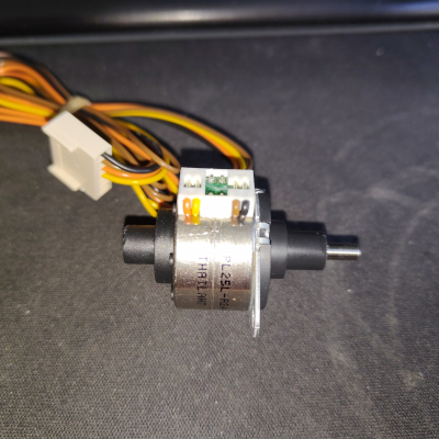
In use, the spectrometer would be represented by an Alpaca remote switch with a digital value field used for position rather simple binary on/off. Thislaoows a separate switch field to control the lamp on/off. Other alternative methods include treating as a focuser with a digital index field for position. Im aware that there is a Shelyak activity under way to provide their own custom driver for their device which has three motors, one for focusing the imaging camera, one for selecting the slit width and one for rotating the grating.
for mine, I'm assuming that the imaging focuser remains constant once set except for the thermal expansion variations. These have not been assessed. The grating I will select as an optimal width for normal seeing - probably 20 or 40 microns which represents 2-4" at 2000mm focal length This is mosntly due to the fact that the slit wheel is hard to turn manually so a motor will struggle with significant re-engineering. Most of that struggle is due to the indexing ball bearing being stuff so potential that couls be removed if motorised. A wider slit sacrifices hard won resolution for optical throughput and increased potential background pollution.Overall the cost of this project has been