
|
|
|
![]()
Making a Flatfield Lightbox


Following discussions on the web regarding flat fielding mechanisms ranging from twilight sky exposures to stretched white shirts to more elaborate light boxes I decided I needed to do something - my exposures were inproving on guiding and thus duration and the dust doughnuts were becoming more prominent because I could now image fainter items of lower surface brightness. Also the vignetting of field is easily seen. So I began collecting the polythene corrugated sheets used in supermarkets to separate trays of milk in the fridges. These are 20" by 12" or so. I collected about 8 of these for nothing while shopping I also happened across some rigid polythene foam packing of 8" internal diameter, 10" external used for packing on something that was delivered to my home. Putting this all together I applied a lot of hot-melt glue-gun glue to knock up a flatfield box that fits snugly on the end of the telescope. The steps were:
This leaves the top. The top I actually bought a nice coated foam cell sheet from Hobbies hobby materials store - its 3mm thick foam card and quite consistently matt white in colour and quite opaque. This was cut to a square and glues to the end flaps. The light source was added - these are a set of 10 pea bulbs, again from Hobbies which attach to a battery holder. The bulbs were hot glued by their leads to the the edge of the the ring and the battery holder threaded outside of the entire affair and glued to the base of the ring. It has a built-in switch, so there is no wiring to do.
At last to the test. There is a picture which gives nothing away quantitatively but looks quite flat by eye.
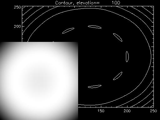
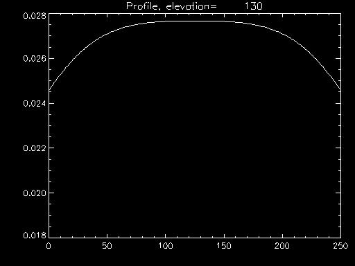
To consider the quantitative flatness of the resulting field imaged into the telescope I created a numerical model The illumination on an object follows an inverse square rule with the distance from the light source For each light in the set of pea bulbs I calculate the distance at a matrix of points on the flat plate. If the pea bulbs are each at position X,Y,X then the distance to each point on the flat plate (x,y,z) is sqrt((X-x)^2, (Y-y)^2 + (Z-z)^2 ). Knowing the distance I can calculate the relative illumination on each point assuming each bulb is the same brightness by adding up the contribution on each point from each bulb. The final part of the equation is to vary the distance between the flat plate and the bulbs in the model (the Z-z distance ) and compare the relative flatnesses of the resulting curves to determine the best distance between the end of the scope and the flat flate for field flatness purposes. The results are below. I think the result needs to be normalised for the variation in brightness due to the varying distance by multiplying by the square of the distance modelled for in order to directly compare the flatness curves becuase the brightness varies as the inverse sqare of the distance.
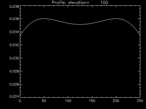
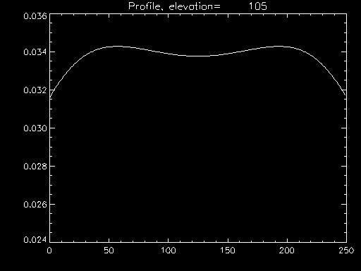
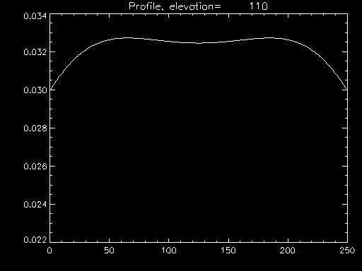
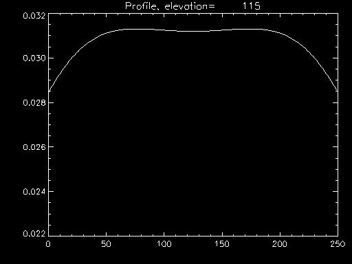
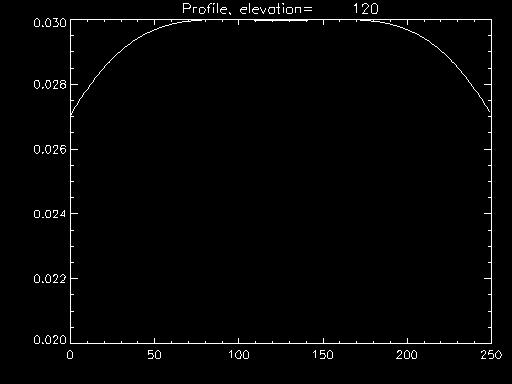
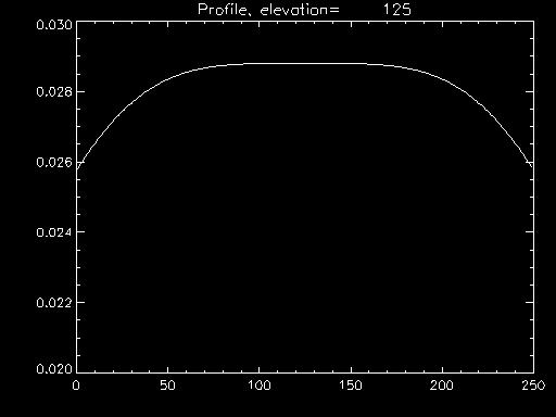
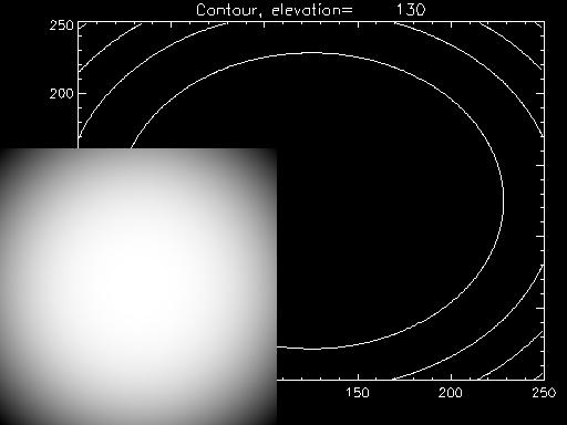
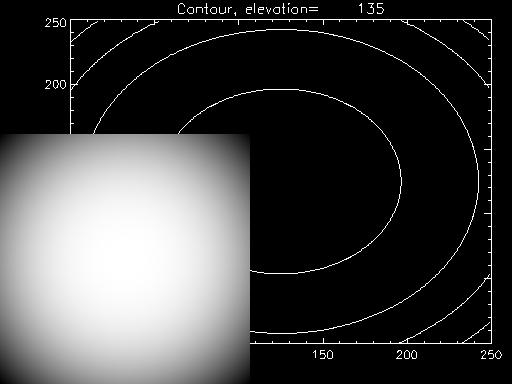
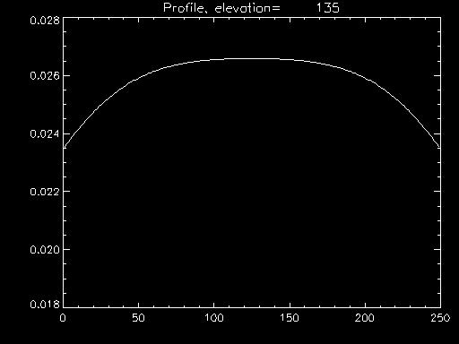
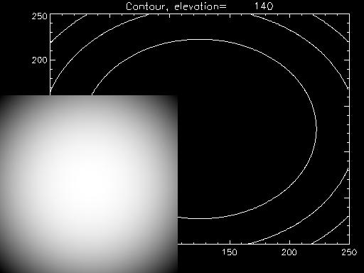
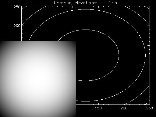
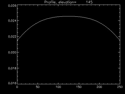
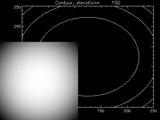
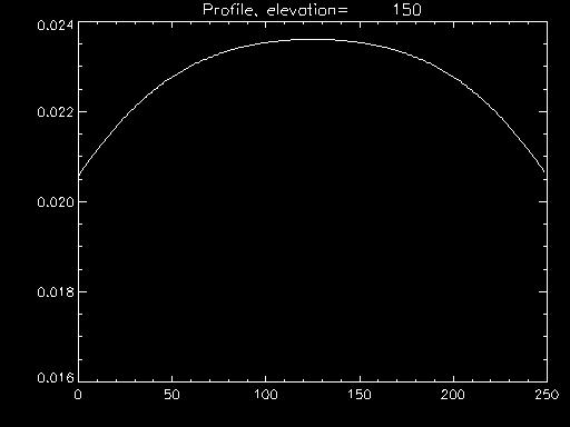
ResultsBelow are the modelled results from a series of IDL models. The first column in the table below shows the contour plot of the iluminated surface for a distance between the lights and the surface indicated by the elevation figure in mm in the contour title. The second column in the table are the intensity profiles across the illuminated surface- they are the cross-sections of plots in column one through the surface of maximum difference between minimum intensity and maximum intensity. Basically they show that the distance from the lights to the illuminated surface should be the radius of the lights circle or very much greater. In this model the radius of the circle of source lights is about 125mm. so the flattest flatfield is achieved at this distance. This model does not take into effect internal reflection from the internal box walls. That would be an interesting addition to the model.
|
|


![]()