Skybadger Observatory
This is the website of Skybadger.net, dedicated to all aspects of Astronomy from the Skybadger observatory : observing, imaging, building instruments and getting results.
This is the website of Skybadger.net, dedicated to all aspects of Astronomy from the Skybadger observatory : observing, imaging, building instruments and getting results.
I had a desire to make a dobsonian for visual purposes - while the observatory is now automated and observes according to the controlling schedule,
I wanted a large telescope for visual use that was portable and easy to use.
Having already bult a 12" f/6 on a horseshoe mount and realised the downsides as well as the upsides of the design ( poor observing angles, high point of balance etc )
I wanted to try bulding something as low to the ground as possible to make handling as easy as possible for a large-ish mirror telescope.
This means fast f-ratio to keep the tube short and manageable, large aperture for light-grasp and design for minimal weight with automation;
this in turn tends to mean truss designs with minimal spiders and secondary cages.
The low rider design for dobsonians brings the centre of mass and height of observing position as low as possible by attaching the
altitude axis bearing surfaces to the mirror box itself, sinking it down low above the ground, higher only than the ground board and azimuth bearing.
To bring the eight this far in means the seocndary ring has to be really light. The use of a wire spider minimises the weight of the
spider itself in the secondary cage at the end of the long lever arm of the telescope truss tube. The focuser weight
and any camera is unavoidable so needs early consideration for balance.
The intended scope is to use a 16" f/4 or f3.5 mirror, no greater than 35mm thick.
I re-used a bunch of ideas I had while building the 12" f/6 horseshoe Newt, especially in the secondary cage and mirror levelling plates.
In pursuit of low weight I designed and 3-D printed the wire tensioner mounts which use guitar tuning heads to tension the wire for the spider,
the truss tube ball mounts and the mirror collimation motor adjustor mounts as part of this project.
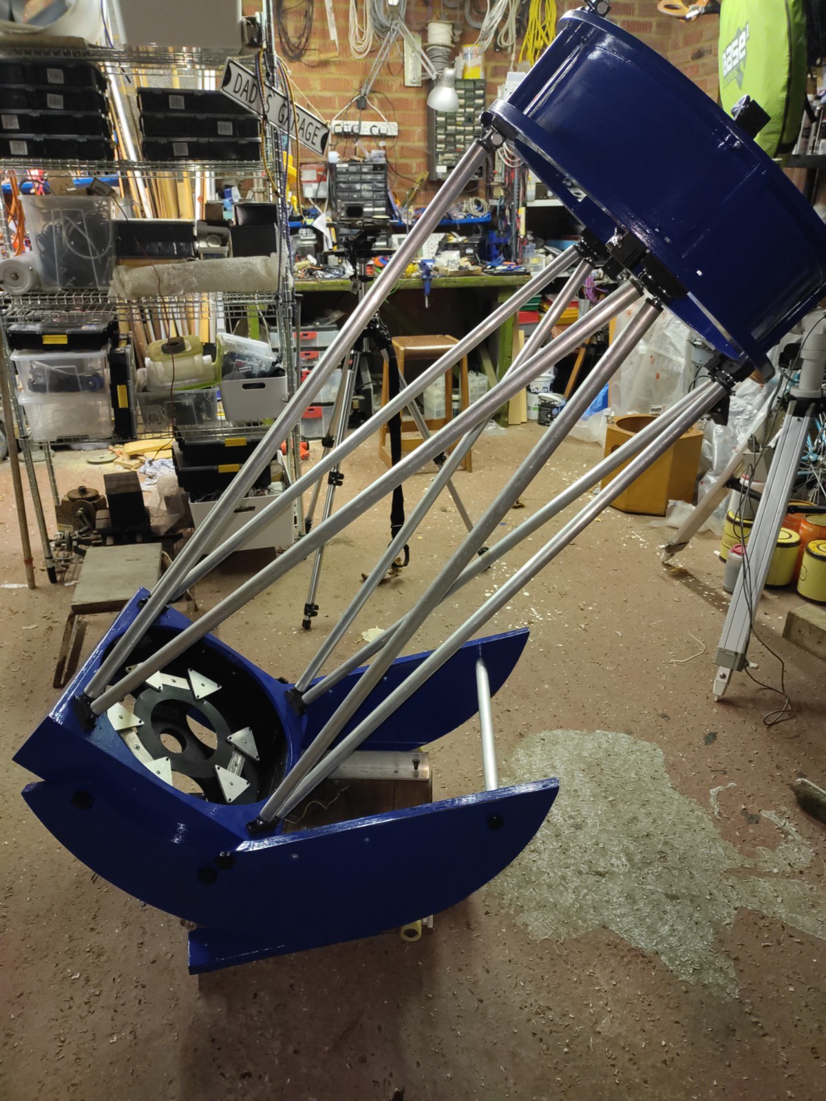
The completed telescope mount, painted deep epoxy blue.
Components
The mirror for this scope is a perforated 16" (400mm) by 25mm thick float glass paraboloid of f/4 focal ration - i.e. the focal length is 64" or 1600mm.
The scope mirror box only takes about 1" of this optical path.
The secondary ring is 6" deep and 18" wide so the optical path consumed by the secondary is
9" for the diameter to the base of the focuser +
3 inch for the half-depth of the ring +
4" for the fcouser body depth +
2" to provide some camera back-focus.
which takes 17" off the focal length that the trusses need to support - ie 64" becomes 48"
The secondary mirror I had in my spare secondary mirrors box and is 3.1" across the minor diameter which is a little bit small but minimises the secondary shadow while
getting a good balance of vignetting (field illumination) vs obstruction.
The base board of the whole mount is simple chip board kitchen worktop, varnished usng thinned varnish for sealing before epoxy painted. This is drilled at three places around the edge for base levelling feet using M10 threaded inserts which are also glued in. The base board is only as big as required to carry the azimuth board and the slew ring to keep weight down and stiffness up. The slew ring bearing is 16"/400mm in diameter and can carry 100Kg while only being 10mm thick. I have tried it by standing on the whole thing and spinning just to prove it to myself. The slew ring is retained by studs on the upper and lower board facing services to register and prevent slippage, the inner ring is connected to the upper and the lower to the base. This means I can wrap a drive belt around the ring and use a stepper motor to drive the azimuth rotation through friction of the tensioned drive belt on the ring while both controller, motors and cabling are all mounted on the azimuth board. The azimuth board mounts on the slew ring and carries the bearings for the altitude rings.
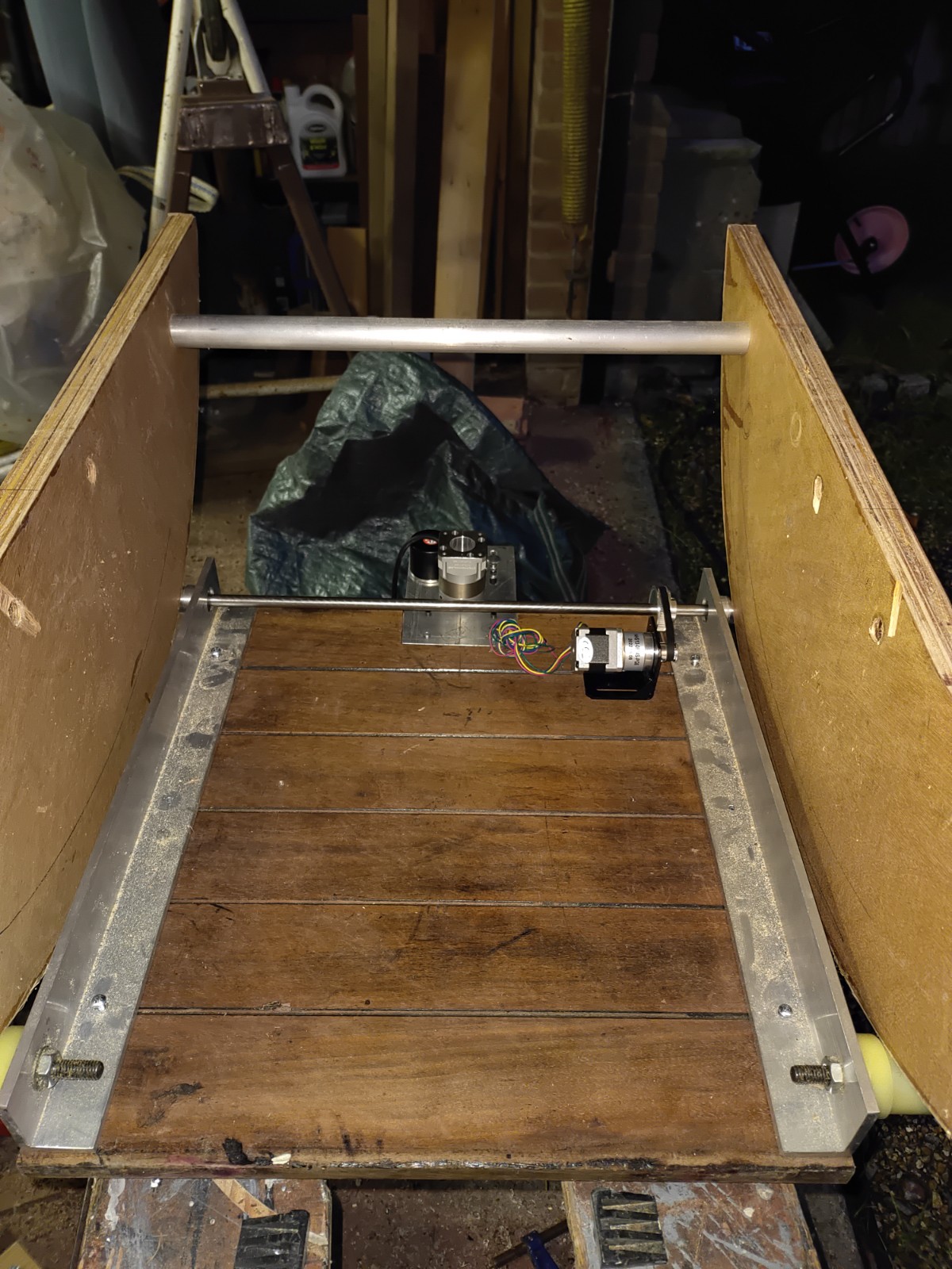
The purpose of the azimuth board is to carry the mirror box and its rocker altitude bearings, providing the second (altitude) axis of
rotation for the simple alt-az mount. I do this using 6mm angle bracket lengths on a spare mahogany ( ie hard and tough) board to carry
, at one end, some stud rollers for the altitude bearers to roll on while at the other end, the angle bar supports flanged bearings and a through-axle.
which is driven by the altitude stepper using timing belt pulleys and also meaured by an encoder using teh seame mechanism.
Each end of this through-axle is capped by a knurled and shaped cyclinder that provides the drive surface to drive and maintain the
altitude by rotating the bearers on the studs through to the chosen angle.
Both the studs and the knurled end caps are shaped with a recess that is the width of the bearer cross-section to keep the bearers aligned.
The distance between the driving end caps and the stud rollers is 10", to provide a good separation of distance for stability and
balance while allowing the curve of the board - the sagitta - to extend beyond the sides of the boards to keep things low.
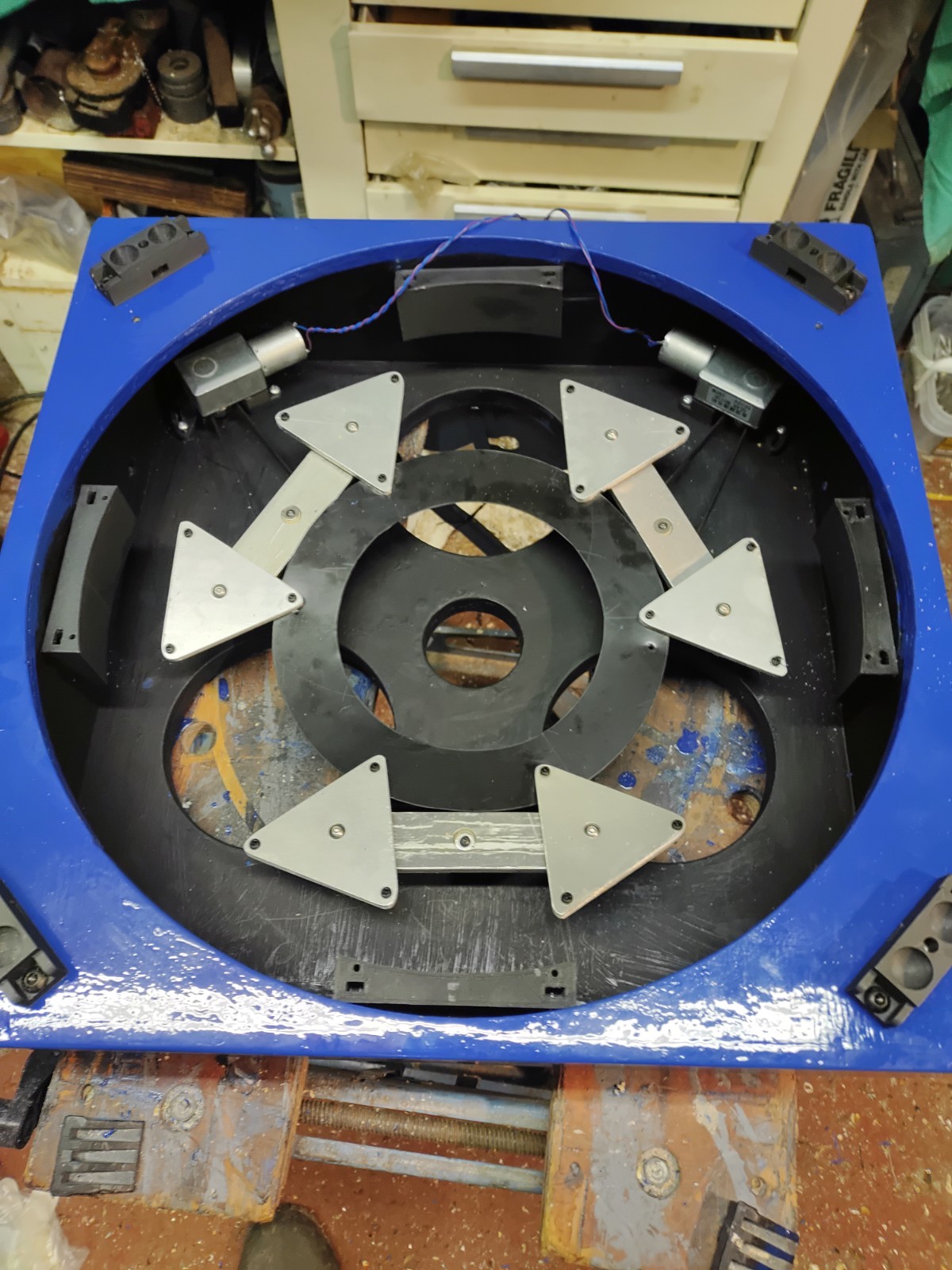
The mirror box is one of the major structural elements of the scope. It provides the mounting points for the truss tubes,
holds the mirror and its mounting components and is the fastening surface for the altitude bearing arcs.
It's relatively straight forward to create the right sized box for the mirror. I routed and glued 1/2" pine box sides
with plywood top and bottom inset into the sides. The bottom has three circular holes cut for ventilation of the mirror and through-bushes inserted for the
M8 threaded shafts which mount the mirror support plates.
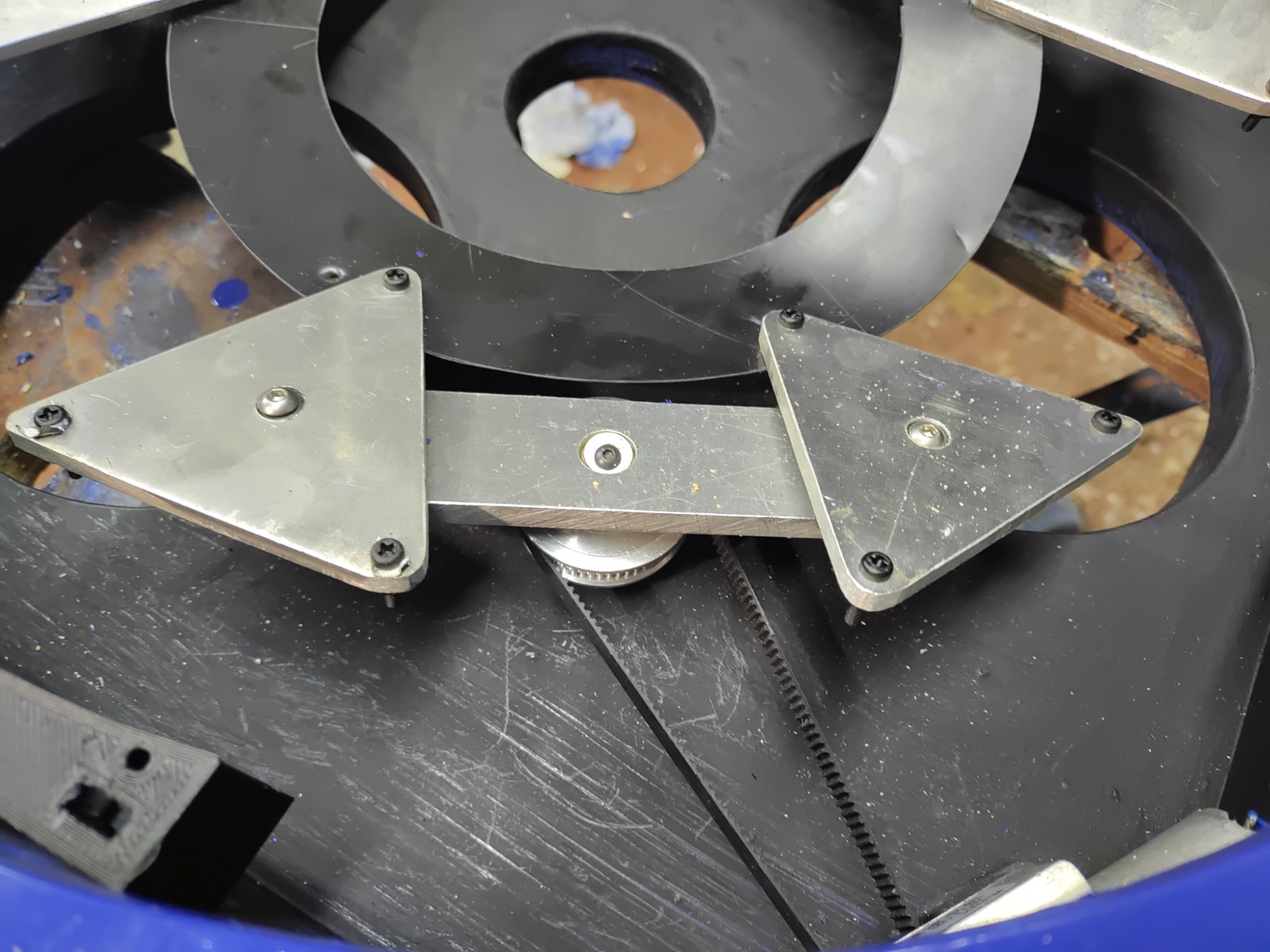
The telescope mirror supports are 18-point - 3 pairs of triangles, each mounted on a beam with a spherical bearing in Igus material which rides the top
of a threaded collimation screw stalk. The triangles are held in relative alignment by a circular sheet of ABS bolted to a corner of each triangle.
The remote collimation is provided by rotating the threaded stalks in the bearings, this rotation drives the stalk up and down in the fixed bushes
and the mirror with it. The rotation is driven by pulleys on the stalk of two of the three collimation points, the pulleys are driven by small gear motors off in the
edge of the mirror box. To hold these motors and tension the belting, motor mounts in the box have been designed and fixtures 3d-printed
which mount 2 rpm DC worm gear motors which are locked when not powered due to the worm gear output.
I now have acquired encoded stepper motors for these fittings which will support capturing and returning to the same position rather than adjusting
by feedback solely in the eyepiece. These motors will be driven as part of the onstep driver system, treating them as DC focuser motors.
Beyond that, I am also considering using Alpaca focuser drivers, as it only has to drive a motor to an encoded position.
The bearing arcs look strange in this build because they were salvaged from the horseshoe of my previous horseshoe mount without further messing about.
Each is half of a 36" diameter horseshoe bearing board. They were kept thick for expediency - they are two sheets of 9mm plywood glued together,
surfaced in board edging plastic and routed flush to the edge. These too hgave been sealed with thinned varnish and then epoxy painted.
This means the centre of rotation for the tube is 18", the rear of the mirror box is about 2" inside the outer lip which means the mirros box weight
has a distance about 12" from the centre of balance, while the secondary ring, at 48" from the mirror, sits at 36" outside the centre of balance.
The Mirror box and the secondary cage are made into a structure using truss tubes. The tubes are tyically attached in a myriad of ways, from socketing into drilled recesses, flattening the ends of tubes and bolting, using angle and bolting etc. I have chosen to use pipes as truss tubes, fitted with ball ends and socketing into ball recesses with clamp plates that fastern them tightly in place once locked. This makes removal easy and allows them to settle into position before tensioning. The balls in use are commercial steel from Wixroyd that are screwed and glued into pipe inserts on the pipes themselves. The ball sockets are 3d-printed plastic units which bolt to the top of the mirror box and retain the ball clamp that fastens the trusses tightly into place. The ball sockets support a variety of angles which means I can use them in different telescope designs, mounted on teh mirror box and secondary cage and just need to worry about the length of the truss and not the angle.
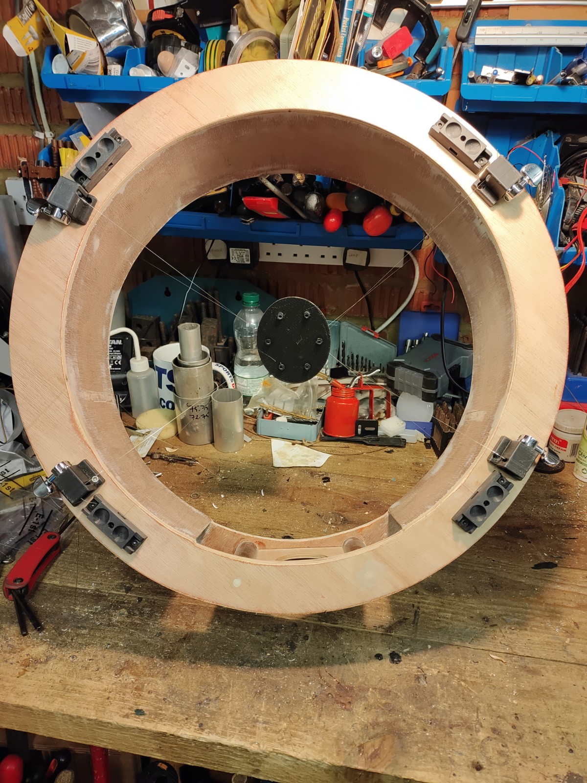
The secondary cage is assembled from two 20" diameter rings of 3/4" marine plywood, of 16" internal diameter. They are separated
by four 5" dowels of 1" diameter and then also made rigid by applying a 3mm plywood inner wall glued against a routed lip on the top and bottom ring surfaces.
Since the longest length I could obtain of the 3mm ply that could bend along the grain was 4', there is a gap I positioned around the focuser.
The holes were filled with body filler and sanded before painting with marine epoxy paint.
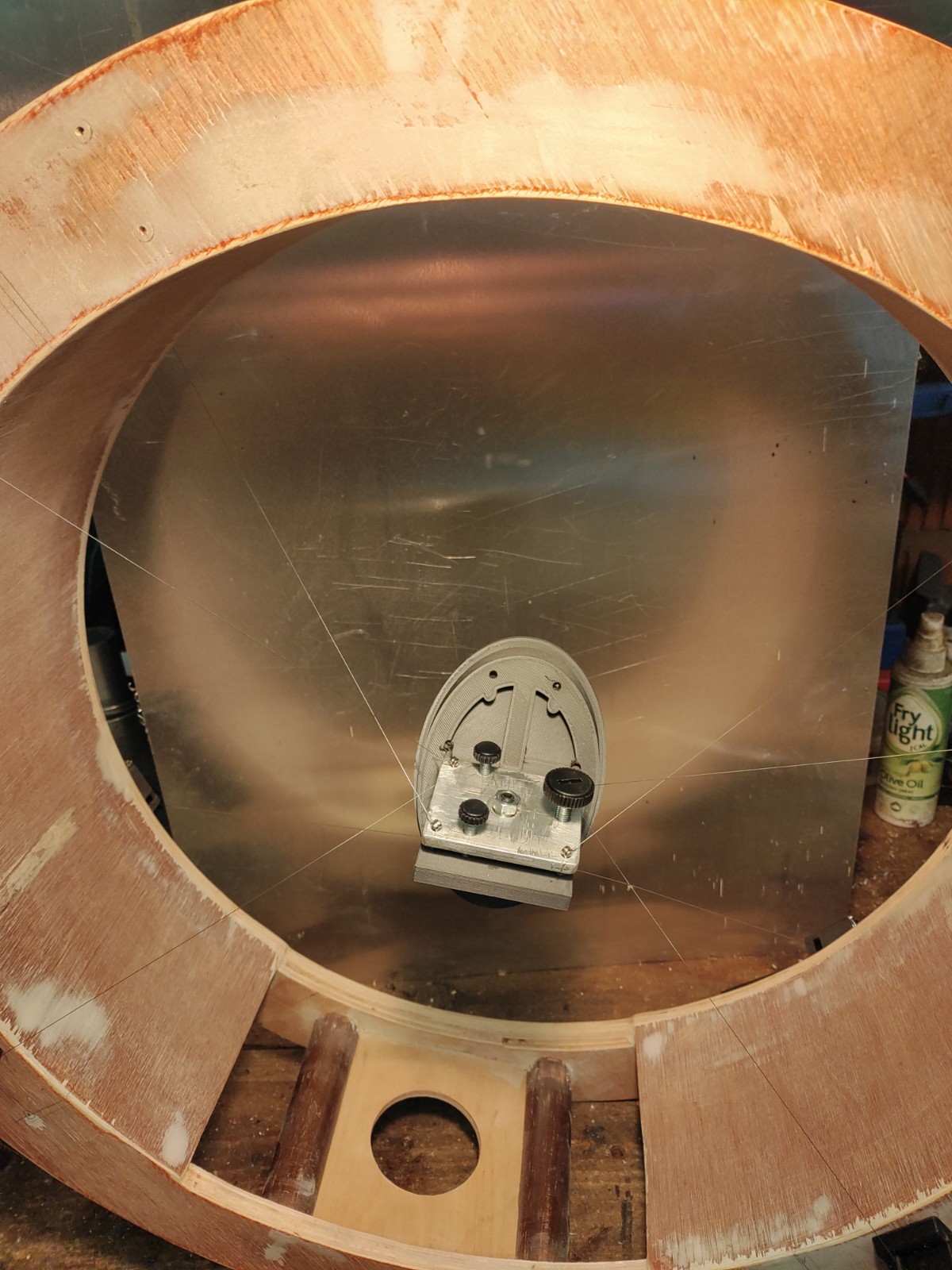
The wire spider design is a copy of a Cloudy Nights design. The point being that the profile of the secondary is to be kept as low as possible while still getting the tension on the spider to keep it stiff against rotation and vibration by crossing over the cables vertically while keeping the wires stiff against rotation of the mirror by attaching to the plate at a distance from the central axis at 45 degrees. x The wire used is guitar E String and the tensioners are guitar head mechanisms for winding the string, mounted on 3d printed mounting blocks to raise the winding handle clear of the woodwork. The wires terminate at a vertical metal plate 3mm thick, 60mm x40mm, wide enough to hold three alignment adjustment screws around the central ball mount which buts against the mirror mounting plate. The secondary holder itself is also 3D printed, consisting of an elliptical mirror backing plate and a 45 degree mounting plate which has built in offsets for the mirror offset during collimation. The benefits of the wire spider include stiffness - ie resistance to vibration and twisting, lightness due to being from very light materials, easy to adjust using the tensioners and a very small footprint of diffraction from the narrow secondary supports to be almost invisible. It's that invisibility that also allows the wires to be insensitive to not being central if you want to use that to provide the mirror offset required for collimating fast telescopes. Ths size of the offset is of the order of 6mm away from the focuser and down the tube for the f/4 mirror. The mirror itself was bonded to the plastic using clear silicon on hard pads on the backing plate which were also drilled through to allow the silicon to ooze out of the back as a means of preventing it just ripping off the backing plate by accident while also preventing big blobs of silicon from holding large areas of glass in tension during thermal expansion as an attempt to minimise any warping of the secondary mirror. The mounting metal plate where the wires terminate are drilled through-hole at the 4 corners, about 5 mm from each side. However when I do this again I will cut a notch from the hole to the edge so the wires can be easily removed if/when they snap, since they are retained by the beads on the end of the wires and this makes it a pain to re-wrap around the guuitar machine heads during replacement due to going through the drilled holes rather than clipping through the the planned recess.