Mirror Making
Mirror making is something I have moved into after owning 3 Newtonian and 2 Cassgrain telescopes.
There's definitely something mystical about bringing a curve into nanometre perfection on glass in your garage.
That said in 2008, a whole 12" [Skywatcher/Meade Dobsonian]telescope could be had for less than the price of a retail 12" mirror in the UK. SO what's the point ?
Well mostly I like to make things regardless of the price drivers ... this is what I am doing
I have a Mirror-o-maticmirror making machine that I swapped with MikeMS for a Newtonian telescope that was no use to me.
With this I have so far attacked a 6" mirror blank and taken it to the polishing stage. This is where I am up to...
Mirror-o-Matic mirror grinding machine
Index
- Introduction
- Building the machinee
- First trials
- Grinding log
- Testing Equipment
- Spherometer
- Mirror mount
- Foucault tester
- Ronchi grating
- Further links
Introduction
The mirror machine came to me as a result of astronomical horse-trading, swapping a large
GEM mount and a 8" Newtonian OTA for the machine as it was and a start kit consisting of two 6" blanks and the
grit, rouge and pitch to manufacture a mirror.
The grinding machine had been built to the design of the mirror-o-matic design of Dennis Rech ( link : ).
While the bulk of the components were in place it wasn't finished : the linkages were not in place, the tool
drive arm was unfinished and a few other bits. However most of the big stuff was in place.
I finished off the machine, building parts and providing linkages from my bits box. For example, the
eccentric driving linkage used a bicycle quick-release clamp to allow rapid hanging of the eccentric motion without tools.


 TOP
TOP
The Testing Equipmentn
TOP
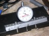
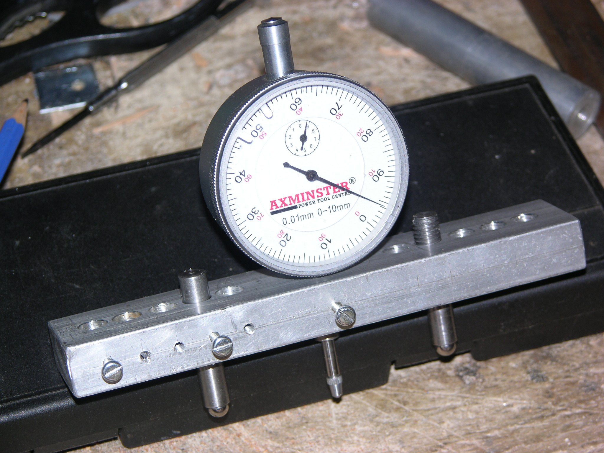
Spherometer
The spherometer is a crucial tool to allow the measurement of the depth of ground mirror to be measured.
This figure, called the sagitta, allows
the measurement of the radius of curvature and thus the mirrors current focal
length by the r&pow2;/2R relationship.
 TOP
TOP
Mirror mount
For testing you need something to hold the miror upright and flat - at right angles tot he testing rig you want to use.
So I made this - its a right angle board with triangle buttresses at the back,
a hole in the middle for when (IF) I eventually get to auto-collimation testing
and the abilty via the two-point strap hanging to accomodate different sizes of mirrors.
The final points are the top mirror clamp to prevent the mirror falling forward and the
rubber blobs on the board to push the mirror forward and flat against its weight in the strap.
![]() TOP
TOP
Foucault tester


 TOP
TOP
Ronchi Grating
TOP
First Grinding log
To setup for a grinding session I needed to provide the mirror mount to hold the mirror on the grinding base and
the tool to hang off the eccentric drive arm.
The mirror mount I provided for by putting three inserts in the grinding table at 120 degrees on a 6" PCD. This allows
any size of mount disk to be bolted into place. The mount disk is mirror-dependent, each different size mirror is expected to use its own.
Each mount disk has routed cuts at 120 degrees in which the mirror clamp bolts sit.
These are cut at 6.3mm and 4mm to provide a ledge for the M4 bolt to clamp to, the 6mm cut stops the nut from spinning.
The clamps hold the mirror centrally on the grinding platter, Freeing one should allow the mirror to be removed, cleaned and reset with out
disturbing the centering.
The tool for grinding was made from cutting a disk to the same size as the mirror from 3/4" plywood and
using duck tape to create a dam around it. The insides were filled with 1" square tile segments set on edge.
Small tile segments were used to fill the odd spaces. These were always on the inside to prevent small bits falling off afterwards.
The tiles were set using a runny cement and water mixture.
Once set, the top of the cement was filed flat and body-filler user to attach it to the plywood disk.
The plywood disk had a bronze bushing socket pressed into the center of the top surface to locate the eccentric drive pin.
The final touch prior to grinding is to cut a piece of carpet to sit the mirror on, on top of the mirror mount.
The single reason for this was that the aluminum angle mirror clamps were taller than the mirror. The carpet provided some grip
and some padding to lift the mirror above the clamps.
The first 6" mirror was rough-ground using this arrangement and tracked using the spherometer ( construction as detailed below ). I found that tool-on-top and full range of
on the eccentric was too much and opted for 1" overhang at start and end of sweep. My powerhead drives the platter at 12rpm for the large one and
23 rpm for the eccentric.
During grinding I put two changes in place - I changed the eccentric for a more-or-less fixed position just off centre
which I found easier to feed grit and water to and changed the tool mount to a swivel foot embedded in a recess in the tool. The first was due to the grinding reaching the right curve so I moved the eccentric to maintain it while it smoothed.
The second was because the rod in the copper bush was too resistant to flexure while following the mirror curves so I wanted something more flexible. The hole was drilled with a normal forstner bit
and the body filler was used to backfill using the foot as a mould so the foot would fit tightly when inserted. Since the foot has a swivel joint I want the foot to be snug and let the joint do the work.


 TOP
TOP
Further Links
- Vacutronics
- Galvopticse
- Oldham Optical
- John Nichol
- Beacon Hill Telescopes
- Stellafane Foucaul Tester
- Win Ronchi Spreadsheet
- Further links
TOP
|