|
|
|
![]()
The Horseshoe mount project
This project is the result of an acquisition from Worthing Astrosoc in early 2010 of their 12“ Newtonian and mount. This telescope they had replaced in their Society Observatory with a 12“ Meade Cassegrain. The telescope consists of a Newtonian OTA bearing a 12" mirror and mounted in a fibreglass tube with a pair of focusers selected by rotating the secondary. The fibreglass tube sits on a wooden sledge which is attached to the bearer on the end of the DEC axis. The dec axis is driven using a hand-made gear hobbed from pulley wheel. The RA axis uses what appears to be a Beacon Hill 14“ worm and wheel running on a 1 1/4" Stainless steel shaft. The underlying mount frame seems to be a piece of industrial machinery pressed into use with some additional pillow block bearings.
I basically bought this for the mirror set and worm wheels to use as a project scope, either by mounting the OTA in the observatory on the large AE systems mount or by re-building and integrating the optics into a completely new scope. In the end, I opted for the completely new scope idea. I had really wanted to take a good look at building a split-ring or horseshoe mount. The benefits of this type of mount are...
- Its stable - all the weight is inside the axles
- Its rigid - the axis distances are as small as can be
- its easy to motorise
- Its low profile in that the end of the rocker box is very close to the ground
- It can be lightweight and portable, though this one isn't..
- It is the nearest thing to a Dobsonian that is still equatorially driven (i.e. it's a dob with tracking platform built in)
- I had the materials to hand
This is what it looked like before I started and while dis-assembling the parts.
 |
 |
 |
 |
 |
The horse-shoe or split-ring
The intention was to size for a 16“ scope and use the 12“ optics in the meantime. The horseshoe or split-ring I cut from a piece of 1.5 “ thick desktop material I had spare using a plunging router on a trammel. It's a 36“ circle with a 16.5 inch; u-shaped slot cut down the centre to within 5 “ of the opposite edge to leave some meat for strength. The U-slot cut is relieved at the corners to a 1“ radius to reduce the chance of crack failure in the wood. The bare edge of the horseshoe will be covered in plastic edging strip attached by impact adhesive to provide an even rolling surface for the horseshoe supporting rollers to support and drive the ring. The wood edge had already been sealed with a few coats of thinned out varnish, soaked into the chipboard.
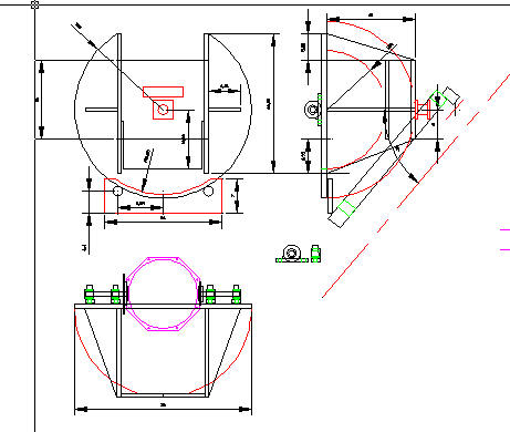
The Polar axis
The polar axis of the horseshoe is a box structure, sized to the full width of the slot and with side stiffening supports out to the edge of the ring. The box needs to be both stiff to prevent splaying and to support the horseshoe now that a big chunk has been cut out the middle. On the back of this box (sized for a swing-through of 12“) is bolted the RA axle. This a wheel hub recovered from a scrap Ford Sierra and bolted directly into place once the brake disk has been removed. More thought is needed about brake disk. I could true it up and use for the RA drive wheel if the horseshoe turns out not be circular enough. This RA box is made from 3/4 “ marine plywood glued and doweled together and then glued and dowelled to the horseshoe.
The rocker box
The box to carry the mirror on the dec axis is also made from plywood. I used 9mm sheet to make the octagonal ends and 6mm sheet for the side. Each of the 8 sides was glued together in pairs using overlapping formers and left to dry in jigs that held the pieces at the right angle before final assembly using the overlapping formers to hold the pieces together while gluing (only). The formers also provide the recessed lip for the top aperture and bottom mirror board. The gaps in the octagonal box were then filled with bodyfiller, sanded and coated in several layers of thinned varnish. The bottom of the rocker box is meant to be screwed on and carry the mirror, hence I recessed 4 sockets for 6mm wide-head socket screws to bolt the back board onto. The Worthing telescope already had its mirror on this type of board, so the issue was just to make sure that I calculated the swing clearance correctly based on the thick ness of board I thought required. The collimation of the mirror is achieved by adjusting 3 through-board screws and also have to swing through the horseshoe and RA box.
The rocker box is suspended on the mid-line of the horseshoe using simple pillow blocks. At the moment I am expecting to just use one each side and have a very small clearance between rocker box and pillow block to prevent the self-alignment of the bearings taking up mis-alignments of the axis of rotation in a non-consistent way. To force the issue I may have to adopt two either side. The axles in each of these pillow blocks are taken inside the rocker box to a bearing hub which uses a compression taper to firmly and concentrically hold the shaft. The bearing hub is bolted to the inside of the rocker box using 6 bolts on a 110mm PCD pitch, the standard for 1610 series shaft hubs. Right now it is only attached using two bolts. Once I am happy that the sockets align and rotate the rocker box normally, I will drill and complete the set. The rocker box upper face will carry the supports for the space frame connecting the secondary box, one in the centre of each octagon face.
The truss tube
The space frame on this mount is intended to keep weight down to a minimum with optimal stiffness and strength. there is no mechanical design to speak off - it uses 1“ 14 gauge aluminium tube with push-in plastic tube inserts at both ends of each. The tube inserts hold a captive M8 nut, into which is threaded a 14mm rod-end ball. The ball at each end of the tube is then held captive in a recess in a piece of strong angle and held there by a metal bar, tightened by a wingnut on a spring. Assembly is insert and tension. Disassembly is undo and pull apart. The recesses are created using a 14mm ball-end milling cutter on a 50 mm pitch between centres. The spring just helps hold captive the balls before final tightening.
The secondary box
The secondary box is made from a pair of disks of 9mm plywood separated by dowels. The dowels are stiffened and hold captive 4 panels of 6mm plywood to provide shadow to the user at eyepiece and a surface to mount the focuser on. The disks have an inner diameter of 16“ for re-use on a 16“ mirror set. The upper surface will support the secondary mirror spider, the lower surface will support the space frame brackets.
The spider is the original re-used. I have re-made the mirror mount though, since the original one wasn't good at holding the mirror (in my hands).
Base frame
The base frame supports the polar axle at the back and the roller plate that the horseshoe rides on at the front. The frame must be capable of being levelled and cope with a small degree of polar axis alteration for polar alignment Mine was intended and expected to be heavy steel and operate like a wheel barrow- a wheel on the end that once put down is no longer in contact with the ground so I can push it to its place of use and set it up fairly quickly with levelling screws and bubble level. Polar alignment is fairly tricky in that both the polar axis and the roller plate need to be able to alter their inclination and typically this a achieved by linking them together through an arc and moving the arc backwards or forwards on rollers to tip the whole telescope up and down.
Motors and encoders
The split ring mount is well suited for motorising to a driven telescope mount. For the polar/RA axis, the drive can be the big horseshoe arc itself or a disk attached to the polar bearing on the back. For the Dec axis drive, a disk or worm and wheel can be attached to one of the axle stubs and driven from a motor mounted on the horseshoe surface, on top or preferably underneath for protection. The other easy thing to do is to attach encoders to these disks to give pointing information even when not driven, so you always know where you are pointing. I have a pair of Magellan encoders standing by for this purpose, purchased from Scopes and Skies Astroboot.
All-up assembly
And this is what it looks like after:
[TO COME!]
Issues
Place to record build issues.
Performance
Place to discuss performance - optical, stability, drive, mobility, weight etc.
Changes
What do I need to change ?
The swing-through distance on the polar axis box is too deep - this is a major system size driver - everything else is scaled to support it.
Links