  Home
  About Me
  My Equipment
  Learning Curve
  Images
 Color Filters
 Emission Filters
 LPS Filters
 RGB Weights

  Contact Me
Learning Curve -Technical Issues The purpose of this page is to summarize some of the technical issues encountered in learning CCD image collection and processing. I am still a beginner, and have made many mistakes. It requires a great deal of patience, and discussion in the user groups to learn tips and avoid making mistakes. I hope some of this will be of help.
Halos Around Stars in CCD ImagesEEver see these donuts in your image? Ever see blue halos around bright stars? I've done a bit of investigating and found some surprising results. They come from various reflections between the filters and camera, within the camera and even within the CCD on certain cameras. Click on the image to see the report.Click on image or here to see Halo Report
Light Box for Taking Flats The following describes the light box recently built for my C11 SCT telescope. The design goals were: 1. Light weight 2. Powered by 9V battery 3. Bright LEDs to take LRGB flats with ~1/3 CCD full-well (~15,000 ADU) in ~10s 4. Uniform illumination It was decided to use two 14" square, white, translucent plastic sheets, 1/4" thick, available locally in plastic specialty stores. 1/4" 30x40" white poster (foamcore) boards were used for construction of the light box. The design and electrical schematic are provided in the following Adobe Acrobat file: LightBoxC11.pdf The white plastic sheets make up the base of the light box, separated by about 5". Two foamcore sheets with a cutout for the C11 are attached to the bottom. White duct tape is used to secure all pieces. The bottom foamcore pieces are slightly larger than the plastic pieces, and serve as a resting point for the top enclosure. The top is made from foamcore and is about 15" tall. Triangles, 7" on a side, were secured into each upper inside corner. They are used as internal diffusers to even out the scattered light. Small 1" boxes made of foamcore hold the LEDs about halfway up each corner. They are wired in parallel and connected to a 5K Ohm linear potentiometer using a 100 Ohm resistor to prevent over- load. The shaft of the pot sticks out of the box and is secured by a knurled knob. Also, leads extend to a 9V battery held on the outside of the box near the knob. An on-off switch can be used. If not used, then disconnect the battery leads when not in use since the circuit will draw down the power of the 9V battery over time. The top assembly slides down over the base. All electrical parts were purchased from Radio Shack, and the part numbers are identified in PDF document. Total cost was estimated at about $40 USD. Each LED was about $5. Each of the plastic sheets and the poster boards were also ~$5. You will need a good razor blade knife and a soldering iron. In retrospect, it may have been better to use black poster board. It would be more star-party-friendly. The white box can be spray- painted black, if necessary.Base showing top plastic piece and slightly larger bottom . A 12" ruler is provided for scale. The larger bottom piece contains the cutout that fits the outer diameter of the telescope, in this case, an 11" Celestron SCT.
Bottom of base, showing bottom plastic piece through cutout. Be sure to tape completely around the cutout to prevent foam particles from being dislodged. They will cling to the plastic by static charge and will appear as dark spots in the flat image.
Inside view the top unit. Note the 7" triangular inserts in each corner that act as light diffusers. Each white LED is contained in a 1" foamcore box about halfway up the sides in each corner. You can see the leads here (longer lead is +). The pot is on the left wall. Cover the wires with white duct tape.
The bright white LEDs are manufactured by Nichia in Japan. I have downloaded the technical literature on these NSPW500BS LEDs here from the Nichia web site: NSPW500BS.pdf They combine a high quality phosphor with their recently commercialized indium-gallium-nitride (InGaN) blue LED. They found that when blue light from the InGaN die passes through a thin phosphor coating, a portion of the blue light is down-converted to yellow light. This yellow light mixes with the remaining blue light to create a bright white light.
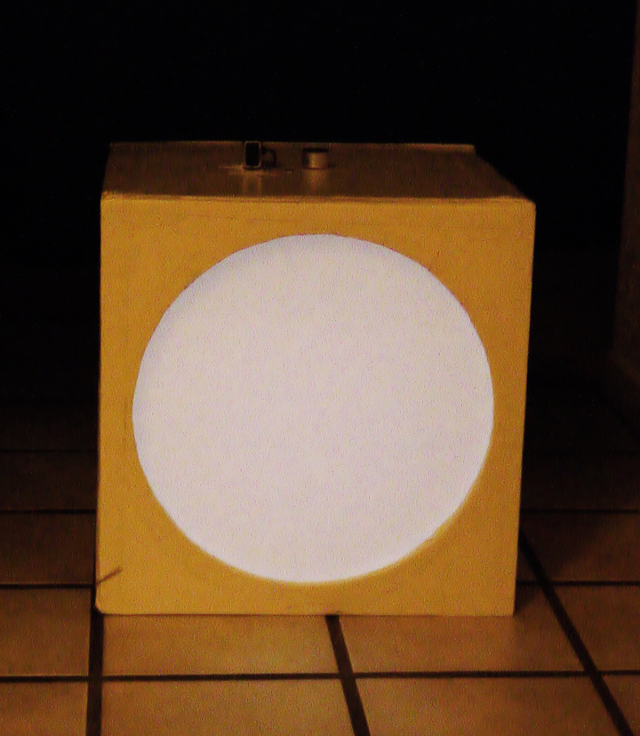
This image show the light box on its side at full intensity with a fresh 9V battery.The emission spectrum of this bright white LED is shown here from the PDF document. It shows the blue emission from the InGaN die at ~ 460 nm and the yellow (shifted light from the phosphor) peaking near 560 nm. There is little blue intensity below 450 nm, whereas astronomical blue filters on CCD cameras extend down to about 370 nm. The yellow shifted light extends to about 750 nm, which covers most red astronomical filters. The color balance of the LED is quite good, as shown in the following chromaticity graph. For my C11, IDAS/Hutech Type III RGB filters and the Kodak KAF3200ME CCD in my FLI camera, my RGB Weight Calculator predicts weights of 0.9:1.0:1.6. These weights, used for astromonical images, provide a white point adjust- ment equivalent to using a sun-like G2V solar analog star. We see sunlight as white. I found that I obtained about 17,000 ADU in 5 s of exposure for the red and green filters using the light box with these white LEDs. I needed 8 s to achieve 17,000 ADU for the blue filter. Thus, I'm getting about the same R:G:B ratios with the light box as I would for a white-point adjusted image of a galaxy. This means that my light box is a suitable device for taking flats for astronomical color imaging.
A flat image taken with this lightbox is shown below. With a new battery, 5 seconds were required to obtain about 17,000 ADU with the clear filter (unbinned on the CCD - CM10ME), about 5 seconds for red and green (Hutech/IDAS Type III -binned 2x2), and about 8 seconds for blue (Hutech/IDAS Type III - binned 2x2). At least 12 flats for each are taken to create a master flat. During the time of image collection, the ADU count did not vary by more than 50 or so. For me, attempting to do this with twilight flats was stressful due to the limited time and concern about rapidly changing light levels. Also, the light box can slide over and cover the BORG 76ED APO guide scope that I also use for wide field-of-view images. Never- theless, I will likely build an inset for the bottom of the light box that will allow it to fit the BORG directly. Lastly, I have made one additional change by placing a connection near the battery for 12V DC input from a modified cable coming from the Gemini control unit for the MI-250 mount, or from a 110VAC-to12VDC power converter. It is wired in parallel with the leads going to the 9V battery.
Don S. Goldman Sacramento, California February, 2003