 |
Remoting the Observatory
Why ?
The purpose of building an observatory is to...
- Provide protection from the elements for the equipment
- Prevent having to setup the 'scope(s) every time
- Weight and complexity of telescope setup
- Re-alignment issues - optical collimation and polar alignment
- Maximise the amount of time available for observing before the wife complains
- Allow increased sophistication of hardware in the timescale available
- Prevent user (me) exposure to the elements.
- Protect the equipment from the kids...
The observatory page details the building of the obbo in so far as the
grunt work of construction goes. Having got to that point the next logical
step is to add the lovely twiddles that allow full remote operation.
The arguments for full remoting go along the line of :
- Remove user error from the observatory to somewhere safe: no trips, bangs, drops ...
- Allow dark-sky operation when you live in the 'burbs
- Remove user thermal contributions to 'dome-seeing'
- Allow multi-user operation across the 'Net
- Add-in fail-safes to control the 'scope when the weather becomes inclement.
- Increase observation time by allowing the observer to go to bed while still observing.
Increasingly remote operation of the observatory is a convenience to allow operation of a telescope under dak skies sometimes
from hundreds of miles away from home, when travelling that distance makes the operational time small by comparison.
We all want dark skies dammit!
More often, remote operation is a convenience to remove the operator from the observatory to prevent vibrations and telescope disturbance during long exposures
where an observer can't actually do anything for tens of minutes at a time.
The first step to remoting an observatory is putting in a remote-controllable telescope. These telescopes are telescopes with electronics control boxes and
position encoders which enable the telescope to move to and track an object by name or location. Nowadays they tend to be able to orient themselves in space
by being manually guided to their first few objects. Once they record the apparent position of these bright and easily found objects, they can contruct a model of their
principal pointing axiis ( ie where North is and where the ecliptic is ) and use this to work out where everything else.
Examples of this type of telescope runs from the introductory-level Meade Autostar ( controls the ETX series all the way up to the LX200 ), the Vixen Skysensor and SkyBook, The Takahashi Temma, Celestron
and then onto the the custom controllers from Boxdoerfer, JMI, Mel Bartels ( great build your-own system ) and AWR of the UK.
Almost all of these communicate with directly to the PC using low-bandwidth serial or USB cables.
Personally I have a modified Autostar 497 driving a Koenig-adapted Vixen SP with a SkyWatcher 150 f/5 achromat and my observatory Vixen GP/DX with Skysensor 2000 carrying a Vixen 8" modified SC.
The next step once you have this level of automation is to use a PC to control the telescope high-level functions.
These functions are provided by telescope planetariums such as TheSky, SkyMap and others. Advanced astronomers with money may well have more software such as
CCDSoft, Orchestrate, HomeDome, TPoint, ACP2 and more. The common denominator to these applications are they provide an
high-level user and programmatic interface to the telescopes or associated hardware they control.
The hardware products associated with this level of control include, but are not at all limited to :
- Focusers : Robofocus, JMI, Meade & more
- Filter wheels : Murnaghan, True Technology & more ( FLI... )
- Auto-guiders : S-BIG, Guide Dog webcam autoguider, Starlight-Xpress & more
- CCD cameras : Starlight-Xpress, S-BIG, Yankee, Apogee & more
- Planetariums : SkyMap, TheSky, Carte du Ciel & more
For example the planetarium programs SkyMap and TheSky provide point and click control of the telescope through a planetarium interface.
Once you connect to the telescope, the telescope follows the mouse to the object you want.
You can then swap to the camera control software which downloads a few 'quick looks' to focus, take a few pictures and then on to the next object. I do not pretend that getting this far is easy - the internet groups are full
of people expressing 'X does not work with Y", "XP drops my drivers" etc.
The advent of the ASCOM platform makes all this easier by providing a
set of interface definitions and code skeleton projects using these definitions. ASCOM defines a set of Windows
Active-X object components that are accessible by executable or scripting languages such as jscript, vbscript, VB, C, C++, .Net, C#, delphi and more.
These objects describe the standard operations on the components. So you can expect to park and direct a telescope, report on its position,
adjust an electronic focuser and take an exposure from a script that talks to these components. Currently you can't access these objects
from Java without a significant chunk of effort and specialised programming knowledge.
Having made the decision to add the bells and whistles what do I do to make it happen ?
However we still haven't removed the source of damage, vibration and possibly worst of all, heat, from the observatory. It has been mentioned in groups.yahoo.com/observatories that
the thermal contribution from a PC in the observatory should be vented as close to ground as possible otherwise all that 350W+ contributes to or even dominates the 'dome seeing' through the slit.
The next level of abstraction of this telescope control capability involves removing the astronomer physically from the building. For some this takes the form of a 'warm outhouse'
which may be a room annex next door to the observatory. This room isolates the heat generated by the PC and the astronomer from the telescope.
In this case, the PC might still be physically connected by wires to all the hardware and the astronomer must still be at the PC to control the proceedings.
Moving on, we want to leave the PC at the telescope and move the astronomer elsewhere. Now this is getting complex. Either we acknowledge that the astronomer must
setup the dome at start of observing such as opening shutters,
removing covers from the scopes and setting up cameras and filters or we acknowledge that all this is permanently setup and things such as covers are
themselves motor-driven flaps and cameras are permanently mounted in dust-tight configurations.
Lets assume that we just want to remove the astronomer, but they are capable of setting up the dome and telescope and closing up at the end.
What is available for the astronomer to control the scope and dome ?
The next options available to the astronomer are limited to :
Implement some sort of network connectivity over TCP/IP to the remote PC.
To do this using current, widely available technology, this normally requires networking the PCs into a small home network with a PC at the telescope and one in the home.
The network can consist of Wireless ( 802.11a/b/g ) routers operating a bridged network across two co-operating wireless hubs, or the observatory pc behaving as a wireless client to a single
wireless router. The first requires two compatible routers to establish the bridge, one at the observatory and one in the home. The second requires a primary wireless router in the home and
a wireless client interface like a pcmcia wireless card or client box connected to the PC via ethernet ( 10/100 baseT/Cat5) to a network cable. these boxes are also available with USB connections.
The range between bridged wireless networks is often greater than between a client and a wireless router but normally no more than 300m when the antennae are raised high, say in the loft.
I have had a pc in my shed at the bottom of the garden 150ft away talking clearly to a wireless router in the loft. I have had a wireless client having a very hard
job of talking to the wireless router 40ft away through 3 walls.
The other trick of expanding the rage of such devices is to use expensive active antennae or the famous Pringles cans to provide a strongly directional signal.
This trick is the basis of a famous web project to provide cheap wirelss links around parts of California over 5km distances!.
Once established at the hardware or system level, the remote connection now needs to connect remotely to that PC using remote control software like RealVNC, UltraVNC, PC Anywhere,
Terminal Server or Windows Remote Desktop connection ( AKA Netmeeting ). The terminal server connection is quite possibly the best option here, for limited bandwidth
it's the fastest in my experience, unless you are really limited and then PCAnywhere is probably the most optimised. Terminal Server des require that the observatory PC be running NT4 server
or Windows 29000 server or Windows 2003 server. None of these really handle
the demands of remote video imaging well though, or full colour depth over a remote connection. For these sort of operations high bandwidth greater than 22Mbp/s would be my estimate
for successful video ( read webcam imaging ) in near real-time and this is not often obtainable over the ranges encountered in this sort of situation.
Implement remote hardware at the observatory that is not a PC but provides TCP/IP connectivity to your telscope hardware.
A good example of this is the hardware solutions available that implement a TCP/IP hub providing serial ports or USB ports.
This is an expensive solution where a hub of this kind can cost Ł200 for 4 ports of any type.
Suppliers of this kind of hardware include Comtrol RocketPort,Equinox and
Moxa . the AQuest AtroHub also falls into this categoryI think but is a slightly odbball solution beingg a custom interface box
with not enough of anything and talking to the pc via USB 2.
the key benefits of remoting these devices are : the reduction cabling : one cable, the increase in transmission speed and distance compared with USB and firewire,
the transparency of the interface : the local pc really behaves as if they are local and the convenience : how else do you get 4 serial ports at the telescope ?
Requirements
The requirements analysis went mostly along the line of :
Q What do I know I can do ?
A Most electronics to the level of surface mount, PIC microcontrollers and PC programming in most languages made this very flexible.
Q What is simple ?
A Serial comms via cable is the most simple. However this is point to point and needs lots of serial ports from a pc to remote, vaguely intelligent devices.
Most PCs provide serial and parallel ports and nowadays even these are being removed in favour of USB ports of different speeds which can be chained to gether for expansion via hubs.
The problem with USB is the distance that the cable can cover is limited without powered repeaters.
The solution begin to look like a two-wire serial link with multi-drop capability. i.e. each device that takes part in the infrastructure is individually addressable
What is available off the shelf and cheap ?
Lots of robotics solutions are commonly available from the web and electronics retailers. These range from motor controllers of all types to motion encoders, IR and visible cameras,
analogue in/outputs inputs in the form of switches and relays and finally digital in/ouputs for measurement via Analogue to Digital Converters (ADCs) and control via Digital to Analague Converters (DACs)
What complicates the issue ?
The fact that the dome rotates makes life a bit hard if the controlling pc for the observatory needs to talk to a device attached to the dome.
The fact that the dome rotates also makes power transmission to the dome devices more difficult.
The distance from the controlling intelligence to the dome devices makes the choice of communication hardware and software dependent on where the intelligence is situated.
In my case a PC in the dome was always a baseline design requirement.
In the end the plans looked like this:
Design
The requirements above lead me to assemble a network of devices all inter-operating using the Inter-IC communications protocol ( I2C ).
This is a two-wire serial connection which can operate at speeds up to 4Mb/sec but most devices handle up to 100Kbp/sec. The benfits of this
protocol are that it supports device addressing,
has lots of standard components on the market,
has lots of hardware and software solutions available on the web to allow the PC to talk I2C
Supports long distance communications
Supports multi-master communications ( ie more than one device can be a controlling device trather than a responding device )
The devices I found for this all pushed me this direction too. Several component suppliers
such as Devasys, FTDI and Active Robotics all provide component hardware that handle most of my requirements.
Devasys provide a USB-2-I2C serial adapter ( I2C ) with lots of digital I/O ( 20 bits )
http://www.dlpdesign.com/usb/provide a USB interface to an intelligent and programmable PIC micontroller
Robot Electronics provide embedded EasyRadio radio serial links with a range of up to 200m ( depending on programmed power output ) which enable
end-to-end serial links over the ether;solving the dome rotation problem. This company also supplies most of the other robotics components I wanted :
a serial fluxgate magnetometer for dome azimuth encoding,
a thermal IR sensor for cloud patrol
Pulse Width Modulation ( PWM ) DC motor
Farnell also provide these EasyRadio Modules as single hardware lumps for embedding in your applications.

Components
The assembly of components came together like this :
 |
Robot Electronics I2C magnetic compass. |

| This device measures the dome azimuth direction to 0.1° with a precision of 1° |
 |
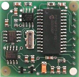
Robot Electronics I2C 10Amp PWM DC dual-motor controller. |
 |
This motor controller provides full speed and direction control of the two dome rotation motors. These motors are
actually car windscreen wiper motors mounted with wheels against the interior rim of the dome. For testing putpose this controller
supports the use of a potentiometer to control the speed and direction of the motors.
The picture shows the controller and LCD mounted together in a weatherproof box. |
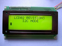 |
Robot Electronics I2C 4 x 20 character LCD display with backlight. |
|
This is used to display the current dome azimuth, shutter state, temperature and the local sidereal time. The display is
updated from the PC by the ASCOM dome control server software which is slaved to the telescope position. |
 |
Phillips 8574A I2C to parallel 8-bit digital interface. |
|
This interface device is a single chip I2C device which provides 8 bits of digital io to monitor the switches used to encode the dome shutter position. |
|
Maxim Max127 12-bit I2C ADC converters to measure dome temperature, external temperature and possibly humidity and rain sensing |
|
This handy device digitizes 8 channels of analogue to 12 bits of digital input, with each channel switchable between bipolar or unipolar 5v or 10v input ranges.
This device as built has the first channel dedicated to
measuring the dome temperature and contains a LM317 temperature sensor. |
|
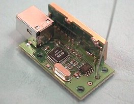
Devasys USB-2-I2C serial interface |
 |
This component ( The large white box in the picture to the left ) provides the I2C interface between the PC and the local I2C serial interface for the fixed devices including the dome motor
controller and the LCD display. The top connector provides about 32 bits of digital IO as well as the in/out serial interface. |
 |
Robot Electronics Usb-to-Serial adapter |
|
This adapter ( The small black box in the picture to the left ) plugs into the PC USB port and appears as another serial port on the PC.
Your PC software then writes to the new serial port and the adapter transmits it at 19200 baud over an EasyRadio link to a EasyRadio receiver.
Here's a sample script I wrote using vbscript on Windows Scripting Host (WSH) to access a remote device ascomtest.vbs
|
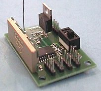 |
Robot Electronics EasyRadio radio receiver module. |
 |
This device decodes the radio-transmitted serial data and transforms it into the I2C serial protocol.
The device provides board connectors for 4 satellite devices. However, since I2C is daisy-chainable, I use 2 connectors only - 1 in and 1 out on every I2C device I build or box up. |
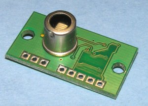 |
Robot Electronics TLP81 thermopile array sensor . |
|
This fantastic device provides an 8-element thermal sensor capable of remotely measuring temperature. What's more, it can also output
PWM control to a servo device to self-scan if suitably mounted! You can then build up a scanned image of the sky temperature
and thus the cloud coverage ( the sky is about -25° colder
when clear than cloudy ). I already had built a servo scanning mounting to scan a webcam using a serial port and a
model servo PWM output device. This device means I no longer need the USB bandwidth or long-exposure modified webcam associated with the webcam sky monitoring.
|
 |
Pan and Scan dome monitoring webcam. |
|
This device was originally built from a kit to provide a servo scanning mounting to scan a webcam using a serial port and a
model servo PWM output device. The purpose was to image the skies with a long-exposure modified webcam to analyse for cloud and inclement weather approaching.
The IR thermopile array does away with this requirement and means I can dedicate a camera to the monitoring of the inside of the dome if operating remotely.
the final addition to his camera would be the removal of the internal IR filter and addition of some IR LEDS to illuminate the interior of the dome
at a wavelength I cannot see but my camera can. This camera is controlled from here : here .
|
|
|
|
|
The application of power to the dome devices has been decided. I decided to use my spare 5W solar panel so I bought a Ł10 charge controller from Maplin and two 4.5AH 6 v batteries to charge in series.
This gives me 6 and 12 V outputs from the batteries and up to 1/2 Amp charging current to top them up again.
I mounted the panel on wooden bearers top and bottom, then velcro-d the whole thing to the shutter. The cable passes around the top side of the shutter
and in over the lip covered by the shutter. So I now have an isolated dome-only DC power supply charging a battery for the
dome devices communicating via radio link. These devices include the dome shutter sensor, the dome shutter motor controller and the dome compass
An alternative to this arrrangement is to have a conductor mounted on the dome-ring
such that when the dome returns to the 'home' position it completes a dome battery charging circuit powered from the dome mains
or battery-backed dc supply.
Construction
Top
|
|