Not sure if this should go in the CAT/CASS forum, but at any rate, I have a 2nd hand set of Star Instruments RC optics that I'm (finally) getting around to building a scope for. I have general info on spacing (and back-focus), but the 20-year-old literature I have says they sent the optimal values for these specific mirrors with them. Well, if I got that info from the original purchaser, I can't find it now.
So, is there any way to find the precise values for these measurements by simple means?
Where are these values measured from on the primary? (The front edge of the primary at the edge of the central hole? The imaginary center of the primary? Presumably the critical point for spacing on the 2ndary is its center.)
Also, if the spacing is off by 1/8" or even 1/4" is that going to lead to very bad results or just sub-optimal, but not too bad results?
BTW: I did fire off an email to Star Instruments asking them about this.
Thanks!
(Getting nervous about the challenge of collimating these mirrors based on what I've read elsewhere....)
John
Precise RC mirror spacing
Started by AlphaGJohn, Jun 21 2013 06:00 PM
33 replies to this topic
#1

AlphaGJohn
-

-
- Posts: 194
- Joined: 12 Jun 2013
- Loc: Wasatch Front, Utah
Vostok 1
Posted 21 June 2013 - 06:00 PM
#2
Mirzam
-
-

- Posts: 4687
- Joined: 01 Apr 2008
- Loc: Lovettsville, VA
Aurora
Posted 21 June 2013 - 06:31 PM
Improper spacing will affect the spherical correction and greatly affect the backfocus. You will need to determine the curvature of both mirrors to determine the design spacing. I'm not sure how to best do this myself with the convex hyperbolic secondary. (Spherometer?) If you have access to a large optical flat you could test both mirrors together in autocollimation to check the system performance.
My modest experience with cassegrains and RC's is that collimation in not too difficult. DK's were the fussiest of the bunch.
JimC
My modest experience with cassegrains and RC's is that collimation in not too difficult. DK's were the fussiest of the bunch.
JimC
#3
AlphaGJohn
-
-
- Posts: 194
- Joined: 12 Jun 2013
- Loc: Wasatch Front, Utah
Vostok 1
Posted 21 June 2013 - 06:43 PM
I was afraid the equipment (and the know-how) would be pretty specialized for such a job. I'm sort of hoping Star Instruments will allow me to send the mirrors to them and have them test 'em (and that they wouldn't charge too much for that).
(Before Star moved to GA, they were within driving distance; not now.)
John
(Before Star moved to GA, they were within driving distance; not now.)
John
#4
Mirzam
-
-
- Posts: 4687
- Joined: 01 Apr 2008
- Loc: Lovettsville, VA
Aurora
Posted 21 June 2013 - 07:06 PM
There are some cassegrain experts on this thread. Hopefully they will chime in.
JimC
JimC
#5
PrestonE
-
-

- Posts: 1893
- Joined: 29 Apr 2005
- Loc: San Miguel de Allende,Mexico
Surveyor 1
Posted 21 June 2013 - 07:21 PM
John, You are looking as tolerances in the thousands of an inch to get the best preformace !!!
Mike Jones is the one to contact on this issue IMHO...
He was of untold help with our 20" RC build!!!
Best Regards,
Preston
Mike Jones is the one to contact on this issue IMHO...
He was of untold help with our 20" RC build!!!
Best Regards,
Preston
#6
AlphaGJohn
-
-
- Posts: 194
- Joined: 12 Jun 2013
- Loc: Wasatch Front, Utah
Vostok 1
Posted 21 June 2013 - 07:30 PM
Preston,
I'm not sure I can figure out a way to measure the distance between primary and secondary to 0.001"s (especially when they're mounted inside a closed tube)!
Is Mike Jones on Cloudy Nights? Do you know his username? Other contact info? PM would be great if you don't want to put his info on the forum.
Thanx!
John
#7
wh48gs
-
-
- Posts: 1840
- Joined: 02 Mar 2007
Surveyor 1
Posted 21 June 2013 - 09:17 PM
Assuming you know system's effective focal ratio and primary's focal ratio, it gives you secondary magnification "m". If you can measure secondary's r.o.c. R2, then you have all you need to get the system parameters. If R2/R1-r (R1 being the primary's r.o.c.), then the mirror spacing in units of primary's f.l. is
s=1-(m-1)r/m
and the back focus, also in units of primary's f.l. is
b=(m+1)(1-s)-1
The p-v wavefront error of spherical aberration due to despace (spacing) error is
W=[1-m^2-(K2)(m-1)^3]d/512(F1)F^3
where "d" is the despace error, K2 the secondary conic, F1 and F the primary's and system focal ratio, respectively.
Vla
- You like this
- Unlike
#8
Ed Jones
-
-

- Posts: 3378
- Joined: 06 Apr 2004
- Loc: Sin-sin-atti
Gemini
Posted 21 June 2013 - 09:49 PM
You would need to know both mirrors radii and conic constants to ray trace them. The primary you could KE test but the secondary would need a test plate or interferometer with transmission sphere; not good choices.
So since both mirror are aluminized (I presume) the easiest way would be to auto-collimate them against an oil flat. You would need to build a fixture and then vary the BFL to find the BFL that gives the least SA using a knife edge or Ronchi. Then in you scope just be sure to hold this BFL.
So since both mirror are aluminized (I presume) the easiest way would be to auto-collimate them against an oil flat. You would need to build a fixture and then vary the BFL to find the BFL that gives the least SA using a knife edge or Ronchi. Then in you scope just be sure to hold this BFL.
#9
Mike I. Jones
-
-

-

- Posts: 3861
- Joined: 02 Jul 2006
- Loc: Fort Worth TX
Soyuz
Posted 21 June 2013 - 10:00 PM
John,
I'm here, we're just out of town for the weekend. The more Star can tell you based on any identifying markings, the better. Let's see what you can find out from them first; it may be enough to assemble your scope for star testing. If not, we can discuss alternate testing methods at that time.
Mike
I'm here, we're just out of town for the weekend. The more Star can tell you based on any identifying markings, the better. Let's see what you can find out from them first; it may be enough to assemble your scope for star testing. If not, we can discuss alternate testing methods at that time.
Mike
#10
DAVIDG
-
-
- Posts: 6770
- Joined: 02 Dec 2004
- Loc: Hockessin, De
Fly Me to the Moon
Posted 21 June 2013 - 11:14 PM
If you can't find the information from STAR and/or don't have the equipment to measure the exact radius of the primary, then all is not lost. What you do is measure of the focal length of the primary using the Moon focused on piece of paper. That will get you close enough so you and/or some of us can give you a pretty good guess at the primary to secondary spacing. Then you can jig up the optics into OTA were you can vary the spacing bewteen the primary and secondary. Now you use a Ronchi screen in the eyepiece with about 100 lines per inch and focused on a bright star so there are between 3 to 5 lines showing. You adjust the spacing of the secondary to the primary until the lines are as straight as you can get them. Now you switch to an eyepiece that has a focal length about the same as the F-ratio of the system and do a star test. You keep adjusting the spacing until you get the inside and outside focus diffraction pattern to match as best as possible. When they match as best as you can get them, your are at the best secondary to primary spacing.
- Dave
- Dave
Homemade 'scopes 8"f/7,6" f/5", 6"f/4, 4.25" Schiefspiegler,60mm Coronagraph,60mm H-alpha system, 4.25" White-light Solar Newtonian,solar spectroscope, 4" f/12, 4.5" f/16 & 6" f/12 Schupmann Medial refractors, 4" & 6" Vintage Fecker Celestars, 21 Stellafane awards, 10 of them in optics, Restoration of the Cook/Hale Spectrohelioscope
Engineering = Taking what you have and making what you need.
#11
AlphaGJohn
-
-
- Posts: 194
- Joined: 12 Jun 2013
- Loc: Wasatch Front, Utah
Vostok 1
Posted 22 June 2013 - 12:47 AM
Thanks to all for your answers! Much appreciated.
I don't have equipment to do any kind of measurements--although someone in the local club or someone in physics dept of local university might.
I should have looked on the backs of the mirrors before asking STAR--they're both mounted in holders so I didn't even think of that; will take it apart tomorrow and see if there's anything there (I know they laser engrave the specs on 'em now, but these predate that practice). Here's the info I do have (general specs for this mirror size from Star):
One trick is that the easiest way to adjust the spacing is by turning the 2ndary holder--but that won't be ideal because one bit of info I did have from STAR (years ago) was that there's an index mark on each of the mirrors (made w/ a marking pen) that should be aligned for best correction. So, turning the 2ndary holder wouldn't be ideal. I'm suddenly thinking of a tool I've seen that has a shaft which can be locked in place or adjusted by micrometer. I wonder if I could contrive to attach the 2ndary to that. Or, I suppose I could get the spacing as good as it would go and then deal with the index mark alignment.
In any case, I'm much cheered to have so much knowledgeable and friendly advice available.
John
I don't have equipment to do any kind of measurements--although someone in the local club or someone in physics dept of local university might.
I should have looked on the backs of the mirrors before asking STAR--they're both mounted in holders so I didn't even think of that; will take it apart tomorrow and see if there's anything there (I know they laser engrave the specs on 'em now, but these predate that practice). Here's the info I do have (general specs for this mirror size from Star):
- 10" f 8.5 (obviously the effective f-ratio)
- Primary Focal Length: 30"
- Back Focus: 12"
- Amplification of 2ndary: 2.90x
- Spacing 19.25"
One trick is that the easiest way to adjust the spacing is by turning the 2ndary holder--but that won't be ideal because one bit of info I did have from STAR (years ago) was that there's an index mark on each of the mirrors (made w/ a marking pen) that should be aligned for best correction. So, turning the 2ndary holder wouldn't be ideal. I'm suddenly thinking of a tool I've seen that has a shaft which can be locked in place or adjusted by micrometer. I wonder if I could contrive to attach the 2ndary to that. Or, I suppose I could get the spacing as good as it would go and then deal with the index mark alignment.
In any case, I'm much cheered to have so much knowledgeable and friendly advice available.
John
#12
MKV
-
-
- Posts: 5319
- Joined: 20 Jan 2011
Fly Me to the Moon
Posted 22 June 2013 - 04:23 AM
AlphaGJohn said
John, while everybody tried to tell you what to do, I think Ed Jones gave you the best answer by telling you how to do it.I'm not sure I can figure out a way to measure the distance between primary and secondary to 0.001"s (especially when they're mounted inside a closed tube)!
The 0.0001" spacing is a theoretical value, but from a practical, hands-on point of view it's meaningless. For your purpose, suffice it to say that when the optics are at their optimum performance they are also at the correct separation. Therefore, your optimal separation is determined optically, and not measured mechanically. In fact, in order to test a Cassegrain's for optimal performance you need not measure anything because it's by definition an optical null test! As Ed Jones noted, you're at the optimal separation when your spherical aberration (SA) is at its minimum.
Now, there are two ways to test your RC optics. One is a star test, under actual night time skies, or using another telescope to produce a parallel beam of light to simulate the star test, and the other one is to test the optics against themselves (autocllimation) by using an optical flat. The latter method doubles observed/visibe errors and is therefore preferred.
At the focus you'd use a simple knife edge (Foucault). Ideally, such a method will give you an "optical null", i.e. what appears as the illuminated mirror (actually it's a shell of converging light wavefront) darkens evenly when a knife edge cuts into the light beam. In reality you'll never see a perfect null, but good optics approach it. At all other separations, the wavefront will appear as a "doughnut". The important thing is -- there is nothing not measure!
Also, remember, that your testing equipment makes all the difference in your results. A precise setup and alignment of components is required using fixtures and a cleverly (kinematically) designed.
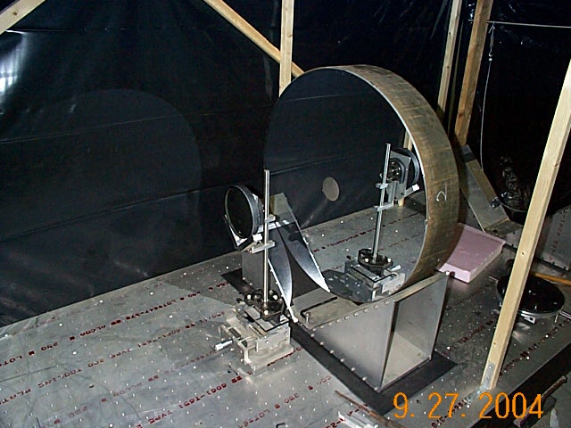
An oil flat Ed Jones mentioned is good for aluminized optics, but requires a vertical setup of the whole telescope. It's more practical to use an autocllimation optical flat (shown testing a cassegrain configuration), which is by definition larger than your primary mirror.
Ronchi grating can likewise be used in conjunciton with an autocollimation flat in place of a knife edge, as long as you remember that this method is the least sensitive one, and really not ideally suited for precision work. It's great for a "quick" assessment, especially the edge and astigmatism, but not for fine detail.
Finally, if you can use an interferometer together with an optical flat that much better, but a good autocollimation setup should be more than good enough, and the best thing is -- there is nothing to measure!

Regards,
Mladen
#13
GlennLeDrew
-
-

- Posts: 14540
- Joined: 18 Jun 2008
- Loc: Ottawa, Ontario, Canada
Voyager 1
Posted 22 June 2013 - 11:34 AM
I should think the optics will perform acceptably over a range in separation of a couple millimetres. Certainly there is no constraint down to the 0.01mm level!
Home-made and modified binoculars
Fabricated astrograph optics for Ceravolo Optical Systems
Create star chart illustrations for SkyNews magazine
My Gallery (mostly DIY stuff)
Simple minds discuss people. Good minds discuss events. Great minds discuss ideas. - Hyman Rickover
#14
Mike I. Jones
-
-
-
- Posts: 3861
- Joined: 02 Jul 2006
- Loc: Fort Worth TX
Soyuz
Posted 22 June 2013 - 12:31 PM
Centration of the two mirrors to each other is fairly critical, however, especially with this f/3 primary. I'll run a tolerance analysis on it in Zemax, possibly today, and post the results. I'll also run the macro that optimizes the baffle tube lengths and diameters.
What is the maximum zero-vignetting field diameter you want, John? Usually 0.8" to 1.0" is enough. Let me know.
Mike
What is the maximum zero-vignetting field diameter you want, John? Usually 0.8" to 1.0" is enough. Let me know.
Mike
#15
AlphaGJohn
-
-
- Posts: 194
- Joined: 12 Jun 2013
- Loc: Wasatch Front, Utah
Vostok 1
Posted 22 June 2013 - 01:55 PM
Hey Mike,
I appreciate the help. I don't know exactly what the appropriate max 0-vignetting field would be. I assume given the curvature of field and other aberrations RC's are subject to that there's no real reason to ensure that absolutely nothing is vignetted. I assume that there's a relationship between the largest diameter of eyepiece field lens you have/plan to buy. (So much I don't know here....)
In general, this is going to be a visual scope (no plans to do more than perhaps stick an old 35mm camera behind it and that's a big maybe). RE the aberrations, probably using it at moderate power will give the best views? Hmmm. Check my PM, if you'd be so good.
John
#16
MKV
-
-
- Posts: 5319
- Joined: 20 Jan 2011
Fly Me to the Moon
Posted 22 June 2013 - 02:32 PM
GlennLeDrew said
Several mm is very generous and can be relized with a simple radius bar. More critically, the exact range can be determined with software. Change the separation by a small amount and refocus to a minimum RMS and see how far that gets you. But some optical engineers may say otherwise and insist on really "tight tolerances".I should think the optics will perform acceptably over a range in separation of a couple millimetres. Certainly there is no constraint down to the 0.01mm level!
regards,
Mladen
#17
wh48gs
-
-
- Posts: 1840
- Joined: 02 Mar 2007
Surveyor 1
Posted 22 June 2013 - 04:29 PM
Sorry, I posted the decenter formula (edited). Taking values for the typical RC system (m~2.8, F~8, K2~-6) gives about 1/15 wave p-v of spherical aberration for each mm of spacing error.
Vla
Vla
#18
AlphaGJohn
-
-
- Posts: 194
- Joined: 12 Jun 2013
- Loc: Wasatch Front, Utah
Vostok 1
Posted 24 June 2013 - 12:31 PM
My question to STAR Instruments resulted in a reminder to check the back of the mirrors--where I found marking pen values I'd completely forgotten about in the years the mounted mirrors have been sitting in the inadequate tube. Here's what I found:
Primary
So, that seems like the info I needed and is substantially different from what I had from the general literature. Thanks for the helpful suggestions--now to the physical issues related to the values (baffle lengths, relative position of primary and focuser, and all the other things I haven't thought of yet). As well as the challenge of achieving optimal concentricity and separation of the mirrors.
John
Primary
- BF 12"
- SP 20 1/2”
- R 6' (at least I assume the mark is ' for feet--odd unit)
- f 9
So, that seems like the info I needed and is substantially different from what I had from the general literature. Thanks for the helpful suggestions--now to the physical issues related to the values (baffle lengths, relative position of primary and focuser, and all the other things I haven't thought of yet). As well as the challenge of achieving optimal concentricity and separation of the mirrors.
John
#19
Ed Jones
-
-
- Posts: 3378
- Joined: 06 Apr 2004
- Loc: Sin-sin-atti
Gemini
#20
Mike I. Jones
-
-
-
- Posts: 3861
- Joined: 02 Jul 2006
- Loc: Fort Worth TX
Soyuz
Posted 24 June 2013 - 05:03 PM
John, you forgot to mention the perforated business card test you performed, which measured the primary ROC to be 62.25" fairly closely. The mirror FL is thus ROC/2 = 31.125", f/3.1125. This is the only reliable value for either of these mirrors at this point.
Simply put, one or more of the Star numbers is/are bogus.
If we use the separation of 20.5" and back working distance BWD of 12" as truth values, we get "p", the distance of the secondary vertex inside primary focus, to be
p = 31.125 - 20.5 = 10.625"
The amplification is then
Amp = [(Primary FL + BWD) / p] - 1
Amp = [(31.125 - 12)/10.625] - 1 = 3.0588X
The system FL is (Primary FL)*Amp = 31.125*3.0588 = 95.206", not 85" as earlier paperwork indicated.
The distance from the secondary vertex to Cass focus is 20.5+12 = 32.5", termed p'. The secondary ROC is thus
Secondary ROC = 2 * p * p' / (p' - p)
Secondary ROC = 2(10.625)(32.5)/(32.5-10.625) = 31.571", quite a difference from six feet!
A few of us here are set up to mechanically measure your secondary ROC, and know how to handle it without scratching the coating. It would be good if you sent it off to one of us for precise measurement. That would be the second true measured known, and could help greatly in narrowing down what you really have and how to space the mirrors. Knowing the ROC for both mirrors doesn't give a single solution, but it does narrow it down to a finite range of solutions.
In reality, it's time to just do this empirically yourself. Get a Ronchi screen, set up the scope looking horizontally, find some very distant point light source, vary the mirror spacing, and refocus at each spacing step until you get the straightest Ronchi bars the optics will give. At that point you've done all that you can to find this scope's sweet spot for usage.
Mike
#21
AlphaGJohn
-
-
- Posts: 194
- Joined: 12 Jun 2013
- Loc: Wasatch Front, Utah
Vostok 1
Posted 24 June 2013 - 05:08 PM
Another dumb question: where do I position the Ronchi screen (which I presume I can just print out on some plastic from the various sources on the 'Net, right)?
#22
DAVIDG
-
-
- Posts: 6770
- Joined: 02 Dec 2004
- Loc: Hockessin, De
Fly Me to the Moon
Posted 24 June 2013 - 05:28 PM
You place the Ronchi were the eyepiece would go. You view a bright star and then focus the Ronchi screen so you see no more then 5 lines, 3 being the best. The lines should be straight and evenly spaced. If not and they are evenly bowing and symmetrical in the pattern then that indicates spherical aberration. So the pattern should look that this ||| if the secondary is in the correct position AND you have well figured optics. If it looks like this )|( or this (|) then you have spherical aberration. If it looks like ))) or ((( then your optics are out of alignment and you need to correct the alignment before going any farther.
You then adjust the spacing of the secondary until hopefully you get straight lines. Each time you move the secondary your going to need to adjust the focus of the grating. A Ronchi test using a star is somewhat of insensitive test so getting straight line means things are good but it doesn't alway mean things are perfect. Now you have to go to star test using a eyepiece with a focal length that is close to the F-ratio of the telescope. So if your scope is f/15 you use a 15mm eyepiece and look at the diffraction pattern of a bright star when it is slightly defocused on both the inside and outside of focus. You then adjust the spacing the secondary which should require very little movement at this point to try to get the patterns to be as close to same on both sides of focus.
Here is a link to "Cassegrain Notes" which has a couple of pages on collimating and using a Ronchi grating to test.
http://bobmay.astronomy.net/CassNotes/
- Dave
Homemade 'scopes 8"f/7,6" f/5", 6"f/4, 4.25" Schiefspiegler,60mm Coronagraph,60mm H-alpha system, 4.25" White-light Solar Newtonian,solar spectroscope, 4" f/12, 4.5" f/16 & 6" f/12 Schupmann Medial refractors, 4" & 6" Vintage Fecker Celestars, 21 Stellafane awards, 10 of them in optics, Restoration of the Cook/Hale Spectrohelioscope
Engineering = Taking what you have and making what you need.
#23
AlphaGJohn
-
-
- Posts: 194
- Joined: 12 Jun 2013
- Loc: Wasatch Front, Utah
Vostok 1
Posted 24 June 2013 - 05:34 PM
Thanks one and all!
#24
Mike I. Jones
-
-
-
- Posts: 3861
- Joined: 02 Jul 2006
- Loc: Fort Worth TX
Soyuz
Posted 24 June 2013 - 06:53 PM
The optical axis goes through the center of the secondary mirror and the center of the primary mirror hole. The Ronchi grating is centered on that axis. You space the mirrors a known amount on the jig, aim at a distant point source, then position the Ronchi along the axis to give just a few bars visible, INSIDE focus.
If the mirrors are too close together, you will see overcorrection in the Ronchi at best focus. Bars bend together toward edge of mirror.
If the mirrors are too far apart, you will see undercorrection in the Ronchi at best focus. Bars bend farther apart toward edge of mirror.
You change the mirror spacing until you find the spacing that gives the straightest possible Ronchi bars. The back working distance is then the distance from the center of the primary mirror to Cass focus.
Mike
Attached Thumbnails

#25
FlorinAndrei
-

-

- Posts: 946
- Joined: 28 Sep 2010
- Loc: California
Viking 1
Posted 25 June 2013 - 11:41 PM
Mirzam said
My modest experience with cassegrains and RC's is that collimation in not too difficult. DK's were the fussiest of the bunch.
JimC
Aren't DK supposed to be fairly tolerant to misalignment, due to the spherical secondary?
Florin Andrei
http://florin.myip.org/
Reply to this topic
CNers have asked about a donation box for Cloudy Nights over the years, so here you go. Donation is not required by any means, so please enjoy your stay.

Recent Topics
-
-
How are you preparing for the total eclipse?
Ed Jones - Today, 11:38 AM
-
 Scopedome "Very dangerous bug" in driver v 5.1.35
keesscherer - Today, 11:36 AM
-
Weird error with a CPC 1100
Go deep - Today, 11:29 AM
-
 Night Vision Observing Report with Boren Simpon 6" f/2.8
Eddgie - Today, 11:25 AM
-
SCT collimation - How often
Ziguy - Today, 11:23 AM
-
Items for sale or trade
patrick77 - Today, 11:21 AM
-
Crescent Moon on April 30, 2017
james7ca - Today, 11:19 AM
-
 Jupiter 01MAY2017 - average seeing
kbev - Today, 11:17 AM
-
Advice on next eyepiece
rdjamieson - Today, 11:07 AM


